**Important -** Please read Safety Informationon proper grounding and electrical safety.
# Front and Rear Panel ### Front Panel [](https://docs.junger.audio/uploads/images/gallery/2026-09/scaled-1680-/Okq3EHgoW6f0r2vd-aixpressor-frontdropshadow-2019-10-2000px-png.png) The AIXpressor front panel provides direct access to the following connections and controls: - **USB:** USB 3.0 Type A connector for removable storage and other supported USB devices - **Headphones:** 6.3 mm (1/4") stereo headphone output - **Display:** 1440 × 240 TFT touch display for local operation and status information ### Rear Panel [](https://docs.junger.audio/uploads/images/gallery/2026-09/scaled-1680-/6gnjfsbfNOAkjKpN-aixpressor-rear.jpeg) The rear panel provides power, network, synchronization, audio I/O, and expansion connections. #### Power - **Redundant Power Supplies:** Two auto-ranging mains inputs with individual power switches - The two power supplies operate redundantly and share the system load during normal operation. For maximum redundancy, connect the two power supplies to independent mains circuits as described in the **Power** section. #### Network - **Ethernet:** Four Gigabit Ethernet RJ45 ports for control, management, and Audio over IP - **LAN 3 and LAN 4** are internally connected through an integrated network switch. The assignment of the network ports depends on the system and AoIP configuration. #### USB and Service - **USB Type A:** One USB 3.0 Type A connector - **USB Type B:** One USB 2.0 Type B connector; currently unused - **Status LED:** Provides a general indication of the system state. Green indicates normal operation. - **Init / Reset:** Service function intended for use in consultation with Jünger Audio support. #### MADI / tieLight Two SFP cages provide the built-in **MADI / tieLight** interfaces. The operating mode of each interface is selected in the software. MADI and tieLight require different SFP module types.Depending on the installed module, MADI connections can be provided as optical single-mode, optical multi-mode, or **coaxial BNC** interfaces.
#### External Synchronization A 75 Ω BNC connector provides the external synchronization input. Supported synchronization formats include: - Word Clock - AES3 / AES11 - Black Burst - Tri-Level Sync #### AES3 I/O The built-in AES3 interface uses a 25-pin D-Sub female connector. It can be configured as: - **8 AES3 inputs / 8 AES3 outputs**, or - **4 AES3 inputs / 12 AES3 outputs** AES3 is also commonly referred to as **AES/EBU**. #### Analog I/O The built-in analog interfaces use two 25-pin D-Sub female connectors: - One connector provides **8 balanced analog outputs**. - The second connector provides **8 balanced analog inputs**, or can be configured as **4 balanced inputs / 4 balanced outputs**. This allows the complete analog interface to operate as either: - **8 inputs / 8 outputs**, or - **4 inputs / 12 outputs** #### Expansion Slots AIXpressor provides four interface expansion slots, **IF 1 – IF 4**, for optional interface boards. Each slot supports up to **64 bidirectional audio channels**, depending on the installed interface module. Available expansion modules include interfaces for applications such as SDI, MADI, Dante, AES3, analog audio, and microphone inputs. # Network Connections #### General Network Considerations By default, **DHCP is enabled on all AIXpressor network interfaces**. When connected to a network with an active DHCP server, each interface automatically obtains an IP configuration. The IP address assigned to **LAN 1 CTRL** is shown on the front-panel display. If no DHCP server is available, a static IPv4 address can be configured for LAN 1 CTRL from the front panel to establish an initial network connection. AIXpressor also supports **Zero Configuration Networking (mDNS/Bonjour)** and can therefore be reached by its `.local` host name on compatible networks.**Note -** The network settings available from the front panel apply to \\\*\\\*LAN 1 CTRL\\\*\\\* only.
**Note -** When integrating the AIXpressor into a managed network, coordinate the required IP addressing and network settings with the network administrator.
#### Accessing the Web Interface To connect using the IP address shown on the front panel, enter the address in a web browser: `https://**Critical information - Please read carefully.**
## Safety Information ### Electrical Safety - **Safety Classification:** AIXpressor is a Class I grounded product and must be operated with a protective earth connection. - **Mains Connection:** Connect the unit only to properly grounded mains outlets. The power cords must remain accessible so that the unit can be disconnected from mains power when required. - **Power Switches:** Each power supply has its own On/Off switch located next to the corresponding mains inlet on the rear panel. The switch positions are marked **I** for On and **O** for Off. - **Redundant Power Supplies:** AIXpressor is equipped with two power supplies and therefore uses two mains power cords. Both connections must be disconnected to completely remove mains power from the unit. - **Protection from Water:** Do not expose the unit to dripping or splashing water. Do not place containers filled with liquid on or directly above the unit. ### Service Safety Service work should only be carried out by qualified personnel. Before opening or servicing the unit: 1. Switch off both power supplies. 2. Disconnect both mains power cords. 3. Make sure that the power cords cannot be reconnected accidentally while service work is in progress. Do not perform service work on the unit while it is connected to mains power unless the procedure specifically requires this and is carried out by suitably qualified personnel. ### Installation and Operation - Install AIXpressor on a stable surface or securely mount it in a standard **19-inch equipment rack**. - When installed in a rack, make sure that the unit is adequately supported and securely fastened. - AIXpressor is actively cooled. Viewed from the front, cooling air enters on the **left-hand side** and exits on the **right-hand side**. Keep these ventilation openings clear and provide sufficient airflow around the unit. - Do not operate the unit with covers or panels removed. - Use only mains power cords that are suitable for the product and approved for use in the country or region of installation. - If the unit, power cords, connectors, or other components appear damaged, disconnect the unit from mains power and have it inspected by qualified service personnel before further use. ### Internal Battery AIXpressor contains an internal lithium battery.The battery must only be replaced with the specified type and by qualified service personnel. Using an incorrect battery type or installing it incorrectly may present a risk of fire or explosion.
# Software installation # Install AIXpressor Software from a USB StickImportant: Use this procedure only when Jünger Audio Support explicitly instructs you to reinstall or replace the software on an AIXpressor system.
This article describes how to install AIXpressor software from a bootable USB stick. The procedure is intended for service and recovery situations and should not be used during normal operation. ## Before You Start Make sure that you have: - The software ISO file provided or approved by Jünger Audio Support - A USB stick suitable for creating bootable installation media - A USB keyboard - Physical access to the front and rear of the AIXpressor - Access to the AIXpressor power supply switchWarning: Creating a bootable USB stick erases the contents of the USB stick. Back up any files from the USB stick before continuing.
## Create a Bootable USB Stick Create a bootable USB stick from the ISO file before connecting it to the AIXpressor. You can use a tool such as [balenaEtcher](https://www.balena.io/etcher/) to write the ISO image to the USB stick. General procedure: 1. Insert the USB stick into your computer. 2. Open the USB imaging tool. 3. Select the ISO file provided by Jünger Audio Support. 4. Select the USB stick as the target device. 5. Write or flash the ISO image to the USB stick. 6. Wait until the process has completed. 7. Eject the USB stick safely.Note: Do not copy the ISO file to the USB stick as a normal file. The ISO image must be written to the USB stick as bootable installation media.
## Connect the USB Stick and Keyboard 1. Connect the bootable USB stick to a USB connector on the rear panel of the AIXpressor. 2. Connect a USB keyboard to the front USB connector of the AIXpressor. ## Start the AIXpressor in USB Boot Mode 1. Make sure the AIXpressor power supply is switched off. 2. Press and hold the red **INIT / RESET** button on the rear panel. [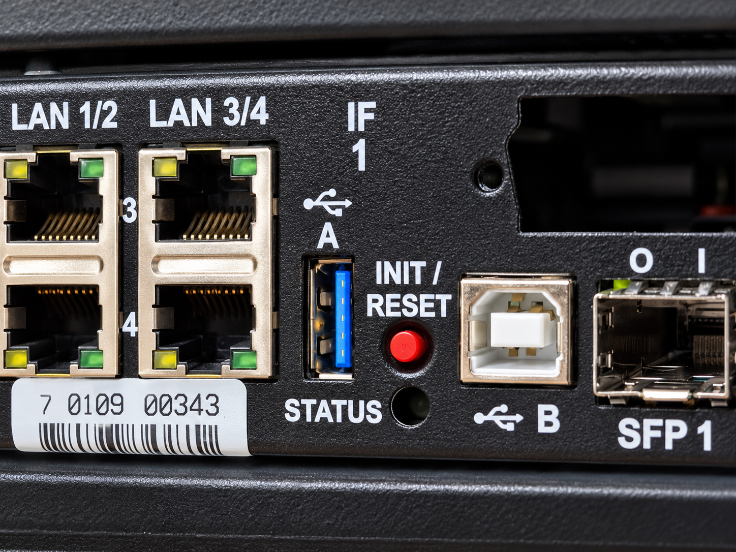](https://docs.junger.audio/uploads/images/gallery/2026-10/SNsBnSqqE51T9QeV-chatgpt-bild-8-okt-2026-16-04-00-4.png) 3. While holding the red button, switch on the AIXpressor power supply. 4. Keep holding the red button until the rear status LED starts flashing blue. 5. Release the red button. The AIXpressor now starts from the USB installation media. ## Start the Installation After the AIXpressor has started from the USB stick, the installation menu appears on the front display. 1. Use the keyboard to select **Install**. 2. Press **Enter**. [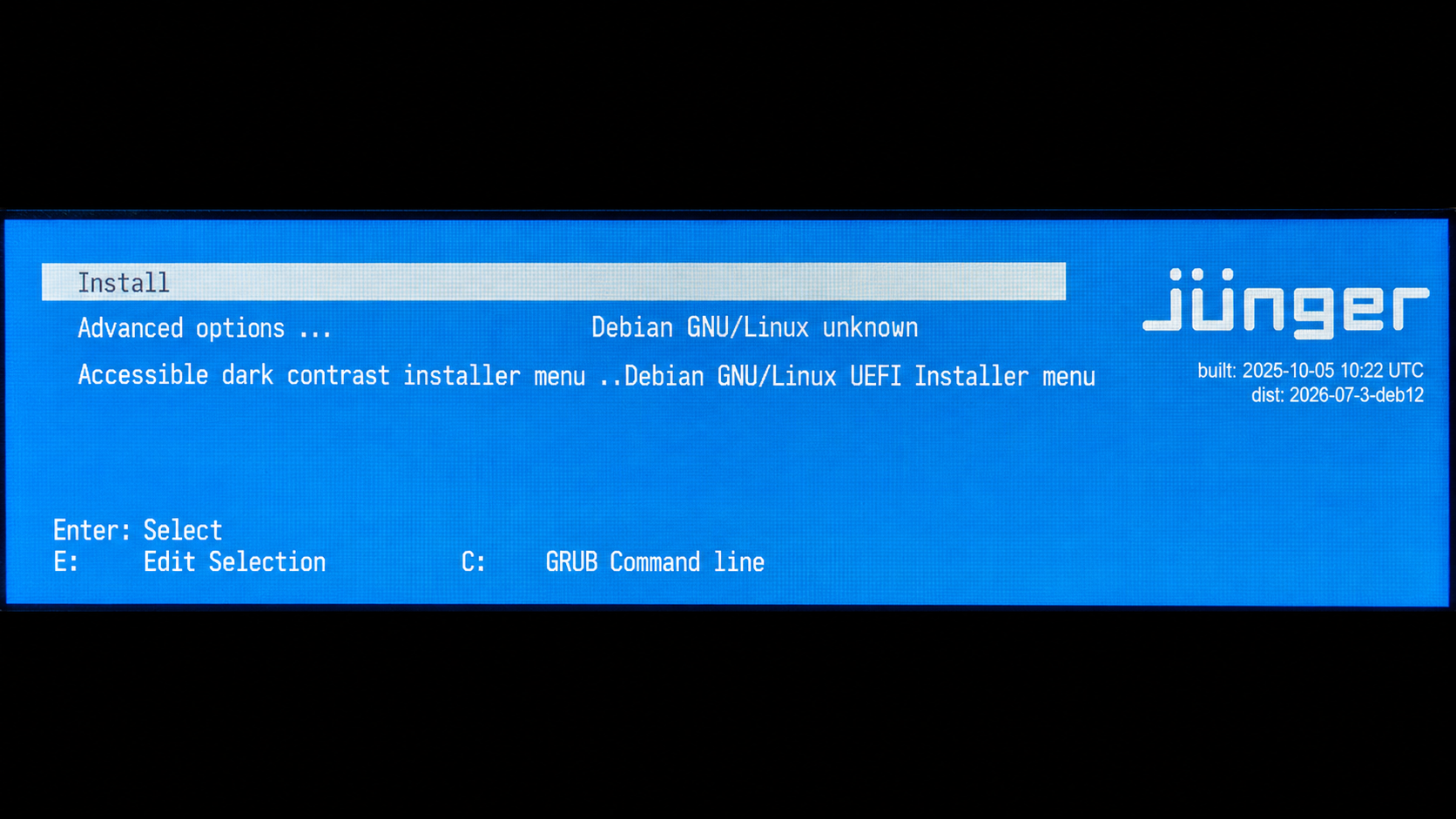](https://docs.junger.audio/uploads/images/gallery/2026-10/VNrsIkV5oKiJRqPk-chatgpt-bild-8-okt-2026-16-03-55-1.png) The installation process starts. Follow the instructions shown on the front display. ## Enter the Host Name During installation, the system asks for a host name. Enter a host name for the AIXpressor. The host name should identify the system in the network. Recommended format: ```text AIXpressor-Important: The power cycle is required after installation. If the system is not power-cycled, it may start in USB boot mode again.
## After Installation After the AIXpressor has restarted normally: 1. Open the flexAI Web UI from a computer in the same network. 2. Log in with the initial credentials or the credentials provided by Support. 3. Check the network configuration. 4. Create or restore the required system configuration. 5. Install or update the license if required. 6. Create a backup after the initial setup has been completed. Detailed information about the first login and basic configuration can be found in the **Connect and Basic Setup** article. # AIXpressor - Technical Data # General - Multi-channel audio processor - Rear panel AES, analog, MADI, tieLight I/O - 3k x 3k cross-point audio router - Front panel headphone jack - Expandable by hardware option boards - Versatile audio processing via licensed algorithms #### Audio Sample Rate - 48kHz - +/- 150ppm sync input capture, +/- 25ppm master-sync stability #### AES/EBU Inputs - Relevant specifications comply with AES3-X-2009, IEC 60985, and AES11-2009 - 4 stereo channels (4 or 2 channel inputs switchable) on D-Sub 25 connector - 24-bit transparent forwarding of PCM and compressed audio without optional SRC (sample rate converter) - 24-bit PCM with SRC activated - Impedance = 75Ohm single-ended - Input level = 0.3 ... 5Vpp @ 75Ohm single-ended - Sample Rate Converter (SRC) = THD+N -120dB @ 0dBFS, 1kHz, latency <0.3ms #### AES/EBU Outputs - Relevant specifications comply with AES3-X-2009, IEC 60985, and AES11-2009 - 4 stereo channels (4 or 6 channel outputs switchable) on Sub-D 25 connector - 24-bit transparent forwarding of PCM and compressed audio - Impedance = 75Ohm single-sided - Output Voltage = 1Vpp (typical) @ 75Ohm single-ended - Power fail relay bypass between AES/EBU inputs and outputs (can be deactivated by internal jumper) #### SFP Sockets - SFP spec, for MADI or tieLight, not for network #### SFP MADI Module - SFP spec, typically 125MBps #### SFP tieLight Module - SFP spec, typically 2.5GBps #### Sync Input - Multi-standard synchronization interface for AES/EBU, Wordclock, or video sync (including black burst and tri-level); complies with AES11-2009 and relevant audio or video standards. - Connector type = BNC - AES/EBU Input = 0.3 ... 5Vpp @ 75Ohm single-ended - Wordclock input = 1 ... 5Vpp @ 75Ohm single-ended - Video-sync input = 1Vpp (nominal) @ 75Ohm single-ended - Supported rates = 23.975, 24, 24.975, 25, 29.97, 30, 49.95, 50, 59.94, and 60 fps (SD and HD) #### Network Interfaces - 4x RJ45 connectors, 1Gbit/s Ethernet auto sense, full duplex #### USB Interfaces - Front and rear USB A 3.0 connectors - Internal USB A 2.0 (for license keys) - Rear USB 2.0 connectors #### Expansion Slots - 4 general-purpose expansion slots for Jünger Audio Option Boards #### Power Supplies - Dual power supplies with automatic fail over - 85 ... 264VAC, 50 ... 60Hz, 58W (max)Network Connections #### Environmental - Operating temperature = 0 ... 50°C, fan cooled - Non-operating temperature = -20 ... 70°C - Humidity < 90% non-condensing #### Physical - 19" x 1RU, 27cm depth - Net weight ca. 5kg - Shipping weight ca. 7.5kg # D-Sub DB-25 Pin Assignments #### AES I/O I/O Mode can be configured in the software to set the physical connectors between 8×8 I/O channels and 4×12 I/O channels. Please note: AES3 is running digital audio in channel pairs (stereo) on one physical pin.| Pin (Female Connector) | I/O Mode: 8×8 I/O | I/O Mode: 4×12 I/O |
|---|---|---|
| 1 | Output Pair 4 + | Output Pair 4 + |
| 2 | Ground | Ground |
| 3 | Output Pair 3 - | Output Pair 3 - |
| 4 | Output Pair 2 + | Output Pair 2 + |
| 5 | Ground | Ground |
| 6 | Output Pair 1 + | Output Pair 1 + |
| 7 | Input Pair 4 + | Output Pair 6 + |
| 8 | Ground | Ground |
| 9 | Input Pair 3 - | Output Pair 5 - |
| 10 | Input Pair 2 + | Input Pair 2 + |
| 11 | Ground | Ground |
| 12 | Input Pair 1 - | Input Pair 1 - |
| 13 | Not Used | Not Used |
| 14 | Output Pair 4 - | Output Pair 4 - |
| 15 | Output Pair 3 + | Output Pair 3 + |
| 16 | Ground | Ground |
| 17 | Output Pair 2 - | Output Pair 2 - |
| 18 | Output Pair 1 + | Output Pair 1 + |
| 19 | Ground | Ground |
| 20 | Input Pair 4 - | Output Pair 6 - |
| 21 | Input Pair 3 + | Output Pair 5 + |
| 22 | Ground | Ground |
| 23 | Input Pair 2 - | Input Pair 2 - |
| 24 | Input Pair 1 + | Input Pair 1 + |
| 25 | Ground | Ground |
| Pin (Female Connector) | Mode: 8×8 I/O | Mode: 4×12 I/O |
|---|---|---|
| 1 | Input 8 + | Output 12 + |
| 2 | Ground | Ground |
| 3 | Input 7 - | Output 11 - |
| 4 | Input 6 + | Output 10 + |
| 5 | Ground | Ground |
| 6 | Input 5 + | Output 9 + |
| 7 | Input 4 + | Input 4 + |
| 8 | Ground | Ground |
| 9 | Input 3 - | Input 3 - |
| 10 | Input 2 + | Input 2 + |
| 11 | Ground | Ground |
| 12 | Input 1 - | Input 1 - |
| 13 | Not Used | Not Used |
| 14 | Input 8 - | Output 12 - |
| 15 | Input 7 + | Output 11 + |
| 16 | Ground | Ground |
| 17 | Input 6 - | Output 10 - |
| 18 | Input 5 + | Output 9 + |
| 19 | Ground | Ground |
| 20 | Input 4 - | Input 4 - |
| 21 | Input 3 + | Input 3 + |
| 22 | Ground | Ground |
| 23 | Input 2 - | Input 2 - |
| 24 | Input 1 + | Input 1 + |
| 25 | Ground | Ground |
| Pin (Female Connector) | Function |
|---|---|
| 1 | Output 8 + |
| 2 | Ground |
| 3 | Output 7 - |
| 4 | Output 6 + |
| 5 | Ground |
| 6 | Output 5 - |
| 7 | Output 4 + |
| 8 | Ground |
| 9 | Output 3 - |
| 10 | Output 2 + |
| 11 | Ground |
| 12 | Output 1 - |
| 13 | Not Used |
| 14 | Output 8 - |
| 15 | Output 7 + |
| 16 | Ground |
| 17 | Output 6 - |
| 18 | Output 5 + |
| 19 | Ground |
| 20 | Output 4 - |
| 21 | Output 3 + |
| 22 | Ground |
| 23 | Output 2 - |
| 24 | Output 1 + |
| 25 | Ground |
**Important** - Not all sample rates are supported by the host system, please refer to the respective information.
#### Inputs and Outputs - 2x RJ45 1Gbit/s Ethernet - Primary and secondary ports configurable as redundant or switched - Inputs = 64 channels @ 44.1 or 48kHz to AIXpressor - Outputs = 64 channels @ 44.1 or 48kHz from AIXpressor #### General Features - AES67 compliant - SMPTE 2110-30 compliant - PTP v2 / v1 sync - Non-audio detection for input channels - Glitch-free Dante / SMPTE 2022-7 audio redundancy # Option Board SDI I/O Option Board SDI I/O (O\_DAP\_SDI\_a) #### Standards - Video complies with SMPTE 424/425M (3G, Level A and B), SMPTE 292M (HD), or SMPTE 259M (SD) - Automatic format detection - Audio embedding and de-embedding complies with SMPTE 299M (3G, HD) or SMPTE 272M -AC (SD) - Metadata embedding and de-embedding complies with SMPTE 2020-2 #### Video Data Rate - 2970/296Mbps (3G), 1485/1483.5Mbps (HD), 270Mbps (SD #### Video Formats - 1080p - 23.975, 24, 25, 29.97, 30, 50, 59.94, 60 - 1080i - 50, 59.94, 60 - 720p - 23.975, 24, 25, 29.97, 30, 50, 59.94, 60 - 625i - 50 - 525i - 59.94 #### Video Delay - User selectable 0 ... 15 frames, can be disabled #### Audio - 24-bit, transparent forwarding of PCM and compressed audio - Sample rate = 48kHz (SDI compliant) - Channels = 16 inputs and 16 outputs (4 groups of 4 channels each) - Delay = Embedder audio delay selectable 0 ... 320ms per channel #### Metadata (RDD6) - 1 channel input, 1 channel output, SDID selectable #### BNC Input - Impedance = 75Ohm - Return loss = >15dB 5 ... 1485MHz; >10dB 1485 ... 2970MHz - Maximum cable length = 250m (SD), 230m (HD), 140m (3G) using Belden 1694A cable - Jitter tolerance = >0.7UI (alignment) #### BNC Output - Impedance = 75Ohm - Output voltage = 0.8Vpp (typical) - Return loss = >15dB 5 ... 1485MHz; >10dB 1485 - 2970MHz - Output jitter = <0.2UI (alignment), <0.5UI (timing) #### Latency - Video latency input to output = 120 ... 200 pixel, depending on video standard - Audio latency input to output, embedder and de-embedder combined = <0.6ms (HD, 3G), <2ms (SD) #### General Features - Power fail relay bypass (may be enabled/disabled via GUI) - Lip-sync compensation for processed and non-processed audio signals - Dedicated routing for non-processed channels; all channels (maximum 16) can be routed to/from the device or looped through - Test pattern generator (no genlock) - Master-sync capable - ITU-R BT.1685 / ARIB STD-B39 metadata support # Option Board 8 Ch Analog Out Option Board 8 Ch Analog Out (O\_DAP\_8DA\_a) #### Audio - 24-bit D/A converter - 8 output channels (for speakers) - Sample rate = 44.1, 48, 88.2, 96kHz**Important** - Not all sample rates are supported by the host system, please refer to the respective information.
#### Analog Outputs - 8 channels - Connector type = D-Sub25 female - Maximum output level (0dBFS equivalent) = 0 ... 24dBu, adjustable in 0.5dB steps - Impedance = 50Ohm (typical), differential - THD+N = -91dB @ 0dBFS = 15dBu, 1kHz - Dynamic range = >103dB (RMS) - Crosstalk attenuation = >103dB @ 0dBFS = 15dBu, 1kHz - Frequency response = 20Hz ... 20kHz (< +/-0.3dB) @ 48kHz; 20Hz ... 43kHz (< +/-0.3dB) @ 96 kHz #### General Features - Power faillure glitch prevention - Balanced analog outputs - Electrical isolation between outputs and device # Option Board 4 Ch Analog I/O Option Board 4 Ch Analog I/O (O\_DAP\_ADDA\_a) #### Audio - 24-bit sigma-delta D/A converter, 24 bit D/A converter - 4 input channels, 4 output channels - Sample rate = 44.1, 48kHz**Important** - Not all sample rates are supported by the host system, please refer to the respective information.
#### Analog Inputs - 4 channels - Connector type = D-Sub25 female connector - Input Level (maximum) 0dBFS equivalent = 0 ... 24dBu, adjustable in 0.5dB steps - Impedance = 20kOhm (typical), differential - THD+N = -93dB @ 0dBFS = 15dBu, 1kHz - Dynamic range = >110dB (RMS) - Crosstalk attenuation = >93dB @ 0dBFS = 15DBu, 1kHz - CMRR = >71dB @ 0dBFS = 15dBu, 1kHz - Frequency response = 20Hz ... 22kHz (< +/-0.1dB) @ 48kHz; 20Hz ... 43kHz (<+/-0.1dB) @ 96kHz #### Analog Outputs - 4 channels - Connector type = D-Sub25 female connector - Output level (maximum) 0dBFS equivalent = 0 ... 24dBu, adjustable in 0.5dB steps - Impedance = 50Ohm (typical) differential - THD+N = -91dB @ 0dBFS = 15dBu, 1kHz - Dynamic range = > 103dB @ 0dBFS = 15dBu, 1 kHz - Frequency response = 20Hz ... 22kHz (< +/-0.1dB) @ 48kHz; 20Hz ... 43kHz (<+/-0.1dB) @ 96kHz #### General Features - Power fail relay bypass between inputs and outputs - Balanced analog inputs and outputs - Electrical isolation between inputs, outputs, and device # Option Board 4 Ch Microphone Inputs Option Board 4 Ch Microphone Inputs (O\_AIX\_4MIC\_a) #### Analog Inputs - 4 channels - Connector type = D-Sub25 female connector - Microphone or line input operation - Microphone mode @ 150 Ohm load: - input-impedance mic: 9 kOhm, electronically balanced - gain range: -10 dB (Pad), 0 dB, 10 dB ... 65 dB - phantom power: +48 V DC, individually switchable per channel - frequency response @ 48 kHz sampling rate: +/- 0.1 dB, 11 Hz to 22 kHz - dynamic range @ 10 dB gain: 115.3 dB RMS unweighted, 118.0 dB A-weighted - equivalent input noise: -128 dB - Line mode @ 40 Ohm load: - input-impedance line: 20 kOhm, electronically balanced - Common data: - analog line channel to channel isolation, 20Hz to 20kHz @ 10 dB gain: min. 118 dB - THD+N @ -3 dBFS, 1 kHz, 10 dB gain: 0,00075 % - THD+N @ -3 dBFS, 1 kHz, 40 dB gain: 0,0075 % - THD+N @ -3 dBFS, 1 kHz, max gain: 0,020 % #### Connector DB-25 Pin Assignment| Pin (Female Connector) | Function |
|---|---|
| 1 | Not Used |
| 2 | Ground |
| 3 | Not Used |
| 4 | Not Used |
| 5 | Ground |
| 6 | Not Used |
| 7 | Input 4 + |
| 8 | Ground |
| 9 | Input 3 - |
| 10 | Input 2 + |
| 11 | Ground |
| 12 | Input 1 - |
| 13 | Not Used |
| 14 | Not Used |
| 15 | Not Used |
| 16 | Ground |
| 17 | Not Used |
| 18 | Not Used |
| 19 | Ground |
| 20 | Input 4 - |
| 21 | Input 3 + |
| 22 | Ground |
| 23 | Input 2 - |
| 24 | Input 1 + |
| 25 | Ground |
**Important** - Not all sample rates are supported by the host system, please refer to the respective information.
### Inputs - 8 channels (4 two-channel inputs) - Connector type = D-Sub25 female connector - Impedance = 110Ohm or 75Ohm, jumper selectable (110Ohm default) - Input level = 0.3 ... 5Vpp @ 110Ohm differential - Sample Rate Converter (SRC) THD+N -120dB @ 0dBFS, 1kHz; Latency <0.3ms ### Outputs - 8 channels (4 two-channel outputs) - Input sample rate converters (SRCs) - Electrical isolation between inputs, outputs, and device (if configured for differential mode, 110Ohm) - AES3 channel status management, non-audio detection - Master-sync capable ### Connector DB-25 Pin Assignment Please note: AES3 is running digital audio in channel pairs (stereo) on one physical pin.| Pin (Female Connector) | Function |
|---|---|
| 1 | Output Pair 4 + |
| 2 | Ground |
| 3 | Output Pair 3 - |
| 4 | Output Pair 2 + |
| 5 | Ground |
| 6 | Output Pair 1 + |
| 7 | Input Pair 4 + |
| 8 | Ground |
| 9 | Input Pair 3 - |
| 10 | Input Pair 2 + |
| 11 | Ground |
| 12 | Input Pair 1 - |
| 13 | Not Used |
| 14 | Output Pair 4 - |
| 15 | Output Pair 3 + |
| 16 | Ground |
| 17 | Output Pair 2 - |
| 18 | Output Pair 1 + |
| 19 | Ground |
| 20 | Input Pair 4 - |
| 21 | Input Pair 3 + |
| 22 | Ground |
| 23 | Input Pair 2 - |
| 24 | Input Pair 1 + |
| 25 | Ground |
**Important** - Not all sample rates are supported by the host system, please refer to the respective information.
#### BNC Input - 65/56 channels @ 44.1 and 48kHz; 32/28 @ 88.2 and 96kHz - Impedance = 75Ohm - Input level = 0.15 ... 0.8Vpp @ 75Ohm - Cable length maximum = 150m using Belden 1694A cable #### BNC Output - 64/65 channels @ 44.1 and 48kHz; 32/28 @ 88.2 and 96kHz - Impedance = 75Ohm - Output voltage = 0.6Vpp (typical) @75Ohm #### General Features - Input cable equalizer for extended range and robustness - Reference-grade Wordclock recover, master-sync capable - Dedicated routing for non-processed channels; all channels (max 64) can be routed to/from the device or looped through - AES3 channel status management, non-audio detection # Option Board MADI I/O, Optical Option Board MADI I/O, Optical (O\_DAP\_MO\_MM\_a, O\_DAP\_MO\_SM\_a) #### Standards - Relevant specifications comply with AES10-2008 and AES11-2009 #### Audio - 24-bit, transparent forwarding of PCM and compressed audio - Sample rate = 44.1, 48, 88.2, 96kHz (88.2, 96kHz short framing)**Important** - Not all sample rates are supported by the host system, please refer to the respective information.
#### Optical Input, LC - 64/56 channels @ 44.1 and 48kHz; 32/28 @ 88.2 and 96kHz - Connector type = LC (IEC 61754-20) - Center wavelength = 1310nm (typical), 1270 ... 1360nm - Input optical power - O DAP MO MM a = -31 ... -8dBm, OM2 multimode (50/125um) - O DAP MO SM a = -23 ... -8dBM, singlemode (standard values, others upon request) - Cable length maximum - O DAP MO MM a = 1.5km, OM2 multimode - O DAP MO SM a = 2km, singlemode (standard values, others upon request) #### BNC Output - Optical and BNC outputs carry the same signal - Impedance = 75Ohm - Output voltage = 0.6Vpp (typical) @ 75Ohm #### General Features - Field-replaceable optical module (SFP) - Reference-grade Wordclock recovery, master-sync capable - Dedicated routing for non-processed channels - All channels (maximum 64) can be routed to/from the device or looped through - AES3 channel status management, non-audio detection - Parallel outputs (BNC/LC) for media conversion # flexAIserver - Overview # Physical Installation**Note -** The information below applies to the pre-configured flexAIserver hardware supplied by Jünger Audio. If flexAI is installed on different server hardware, refer to the manufacturer's documentation for model-specific installation, cooling, power, and safety requirements.
The pre-configured **flexAIserver** is a **1RU, 19-inch rack-mount server** intended for installation in a standard equipment rack. Install the server using the appropriate rack-mounting hardware and make sure that it is adequately supported. The server is actively cooled. Keep all ventilation openings clear and ensure sufficient airflow through the rack. Additional spacing above or below the server is normally not required unless specified by the server manufacturer or required by the cooling concept of the installation. ### Power The pre-configured flexAIserver is equipped with redundant power supplies. Connect both power supplies for redundant operation. If one power supply fails, the remaining supply can continue to power the server. For installations requiring high availability, connect the two power supplies to **independent mains circuits** whenever possible. Ideally, the circuits should also be backed by separate UPS feeds or other suitable backup power arrangements. This provides protection not only against a power supply failure, but also against the loss of one mains circuit. Each power supply has its own mains connection and power control, depending on the installed server hardware.**Important -** Please read Safety Information on proper grounding and electrical safety.
# Software Installation Guide Dell ## Installing flexAIserver This guide describes two methods for installing the **flexAIserver** software on a supported Dell PowerEdge server: - **Method A:** Installation from a bootable USB drive - **Method B:** Remote installation using Dell iDRAC Virtual Console and Virtual Media Both methods use the same flexAIserver installation image. Once the installer has started, the remaining installation procedure is identical. ### Prerequisites Before starting the installation, make sure the following are available: - flexAIserver ISO image. The ISO may be supplied inside a ZIP archive and must be extracted before use. - Access to the Dell PowerEdge server. ### Required BIOS and iDRAC Settings Before installing flexAI, verify that the following server settings are configured correctly.| Necessary Setting |
|---|
| Configuration → BIOS Settings → Boot Settings → Boot Mode = **UEFI** |
| Configuration → BIOS Settings → System Profile Settings = **Performance** |
| Configuration → BIOS Settings → Processor Settings → Virtualization Technology = **Enabled** |
| Storage → Virtual Disks → Layout = **RAID-1** |
| iDRAC Settings → Connectivity → Network → IPv4 Settings → DHCP = **Enabled** |
| iDRAC Settings → Connectivity → OS to iDRAC Pass-through → State = **Disabled** |
**Important -** Installing flexAIserver erases the selected target disk. Make sure that the correct server and target disk have been selected before continuing.
--- ## Method A – USB Drive ### 1. Create a Bootable USB Drive Use a suitable image-writing tool such as **balenaEtcher** to write the flexAIserver ISO image to a USB flash drive: [https://www.balena.io/etcher/](https://www.balena.io/etcher/)**Important -** Writing the ISO image erases all existing data on the USB drive.
When the USB drive is ready: 1. Insert it into a USB port on the server. 2. Connect a keyboard. 3. Power on or restart the server. ### 2. Open the Boot Manager During server startup, press **F11** to open the Dell Boot Manager. [](https://docs.junger.audio/uploads/images/gallery/2026-09/scaled-1680-/a1gf3xY9VDaHhlVO-install0-png.png) **Dell PowerEdge boot screen – press F11 to open the Boot Manager.** ### 3. Open the One-shot UEFI Boot Menu Select **One-shot UEFI Boot Menu**. [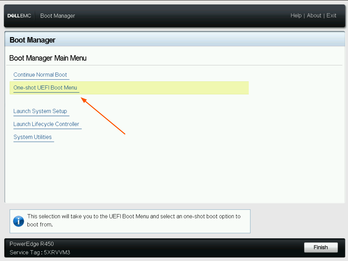](https://docs.junger.audio/uploads/images/gallery/2026-09/scaled-1680-/gUHAIhZbccyPqUVH-install1-png.png) **Boot Manager – select One-shot UEFI Boot Menu.** ### 4. Select the USB Drive In the UEFI boot list, select the entry corresponding to the connected USB drive. [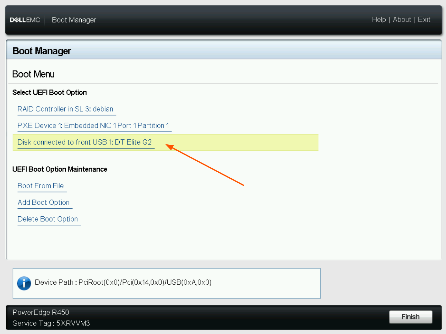](https://docs.junger.audio/uploads/images/gallery/2026-09/scaled-1680-/LXwPWq4h0rCJHHXr-install2-png.png) **Select the USB installation drive. USB installation only.** Continue with **Common Installation Steps** below. --- ## Method B – Dell iDRAC Virtual Media ### 1. Map the ISO as Virtual Media Open the Dell **iDRAC Virtual Console**. In the Virtual Console, open **Virtual Media** and map the flexAIserver ISO image as a virtual CD/DVD. [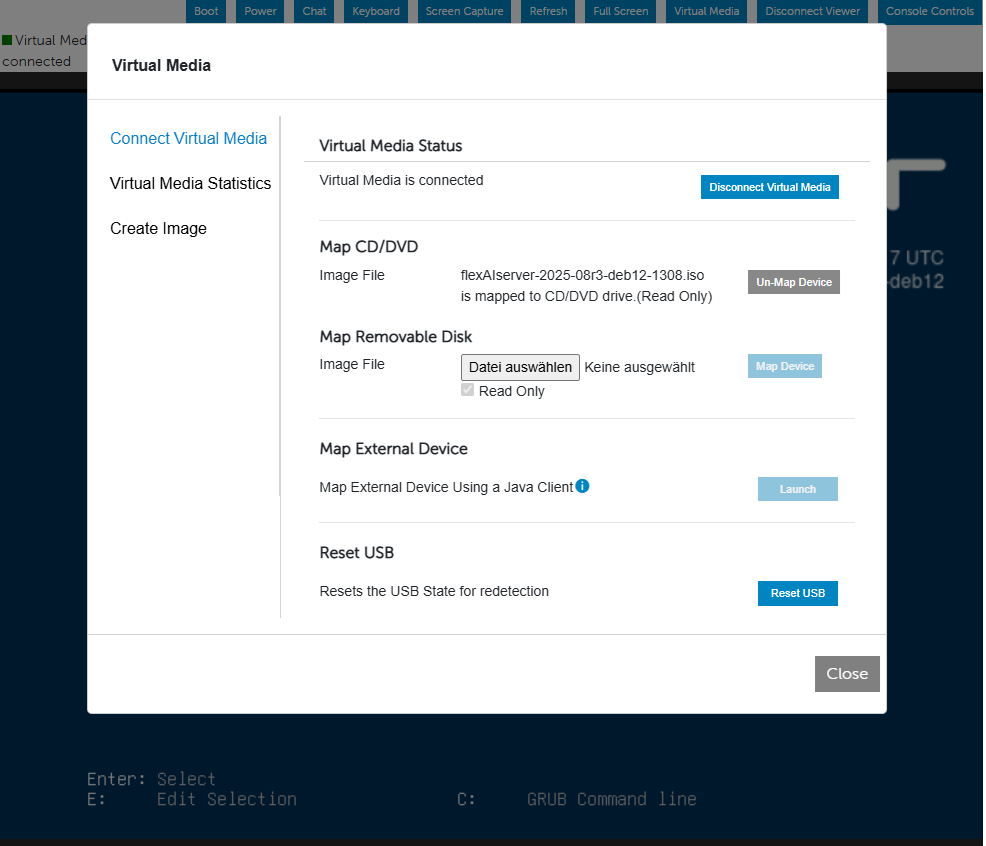](https://docs.junger.audio/uploads/images/gallery/2026-09/scaled-1680-/eJlWyNSMcznwSYmK-idrac-virtual-media-mount-png.png) **iDRAC – flexAIserver ISO mapped as Virtual CD/DVD. iDRAC installation only.** ### 2. Restart the Server From iDRAC, select **Power > Reset System (warm boot)** to restart the server and make the virtual installation media available during boot. [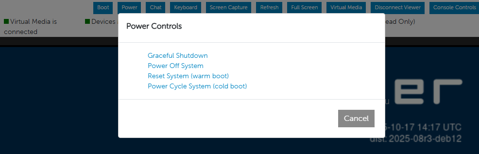](https://docs.junger.audio/uploads/images/gallery/2026-09/scaled-1680-/pzXXMvvF2lXNqZfW-idrac-warmboot-png.png) **iDRAC – restart the server using Reset System (warm boot). iDRAC installation only.** ### 3. Boot from the Virtual Optical Drive During startup, open the **Boot Manager**, select **One-shot UEFI Boot Menu**, and then select **Virtual Optical Drive**. [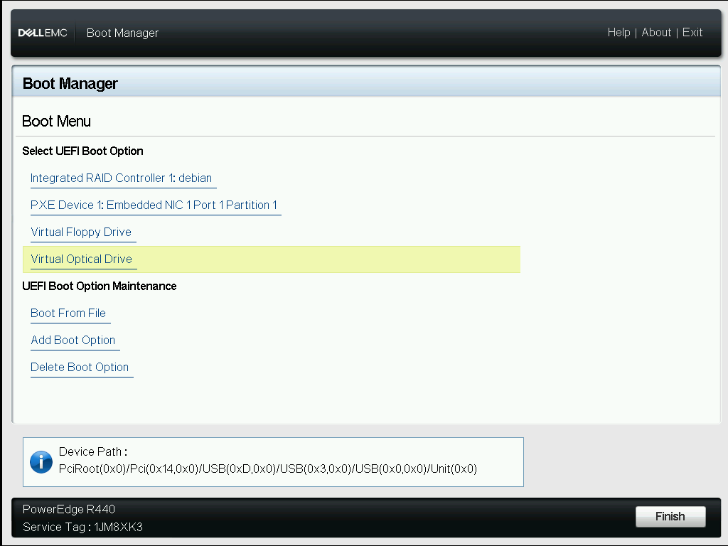](https://docs.junger.audio/uploads/images/gallery/2026-09/scaled-1680-/I76mUSnoPw6bDH0y-idrac-boot-from-virtual-optical-drive-png.png) **Boot from Virtual Optical Drive. iDRAC installation only.** Continue with **Common Installation Steps** below. --- ## Common Installation Steps The following steps are identical for USB and iDRAC installations. ### 1. Start the Installer In the Jünger Setup menu (GRUB menu), select **Graphical install** and press **Enter**. [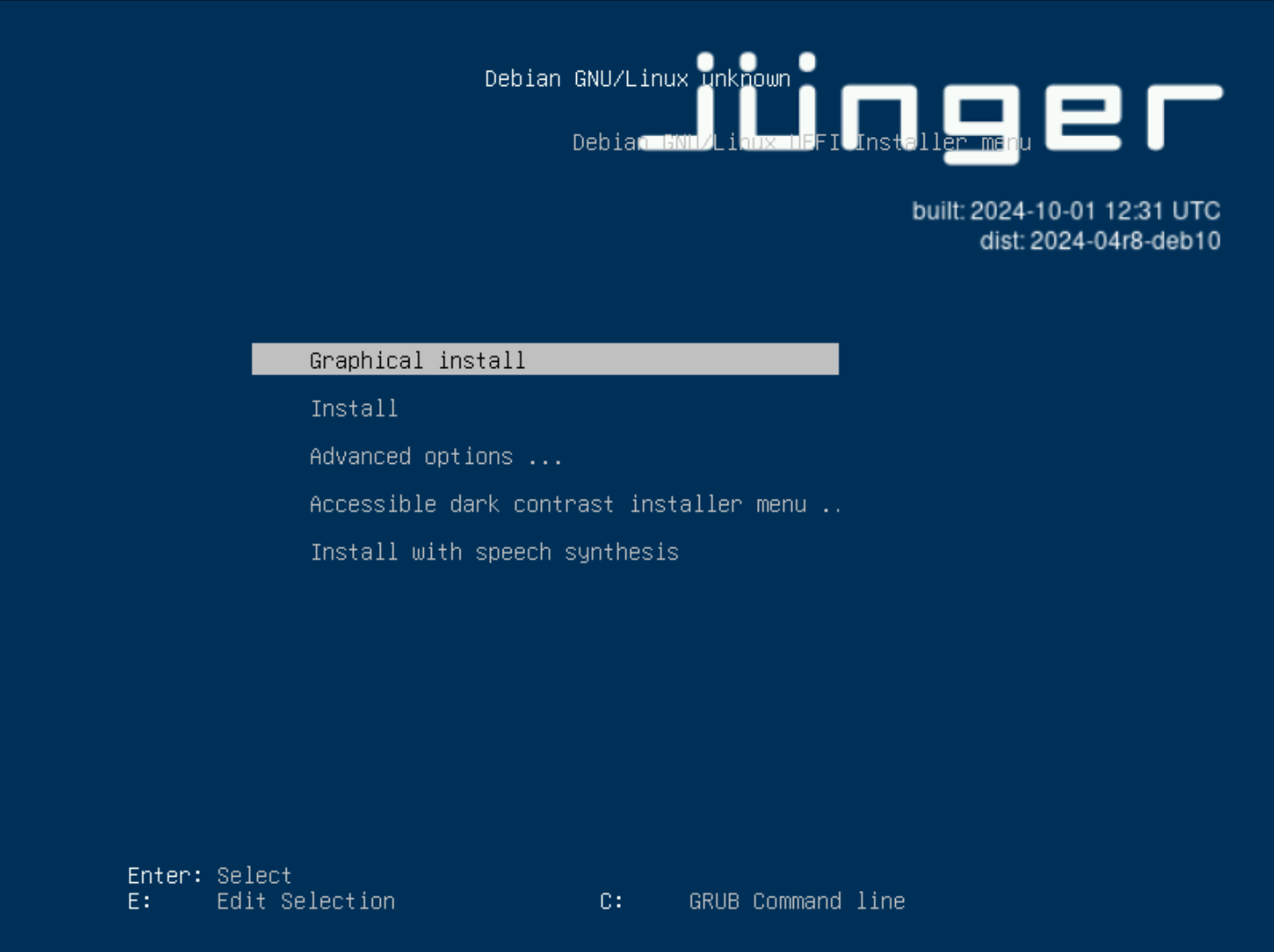](https://docs.junger.audio/uploads/images/gallery/2026-09/scaled-1680-/IvwiJAGJorhWxuMh-install3-png.png) **GRUB – select Graphical install. Applies to both installation methods.** ### 2. Set the Host Name When prompted, enter the host name to be used by the flexAIserver. For a Jünger Audio pre-configured system, the host name can follow the device serial number, for example: `flexAIserver-00119` Alternatively, use a suitable host name according to the naming conventions of your network environment. [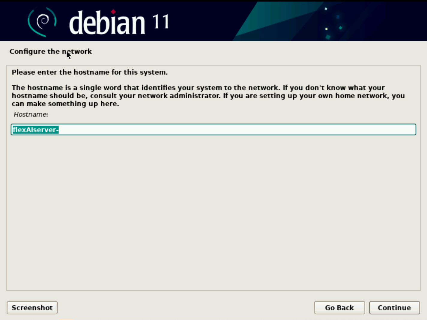](https://docs.junger.audio/uploads/images/gallery/2026-09/scaled-1680-/Ef4PdszcTJ6btFri-install4-png.png) **Enter the host name for the flexAIserver. Applies to both installation methods.** ### 3. Select the Target Disk Select the internal system disk on which flexAIserver should be installed. On Dell PowerEdge systems with a PERC RAID controller, the internal storage may appear with a name such as **DELL PERC**. If you encounter messages such as “Failed to create a file system” or “The following partitions are going to be formatted:”, select “Continue” and then “Yes” when asked “Write the changes to disk?”. For USB installations, make sure that you do **not** select the USB installation drive. [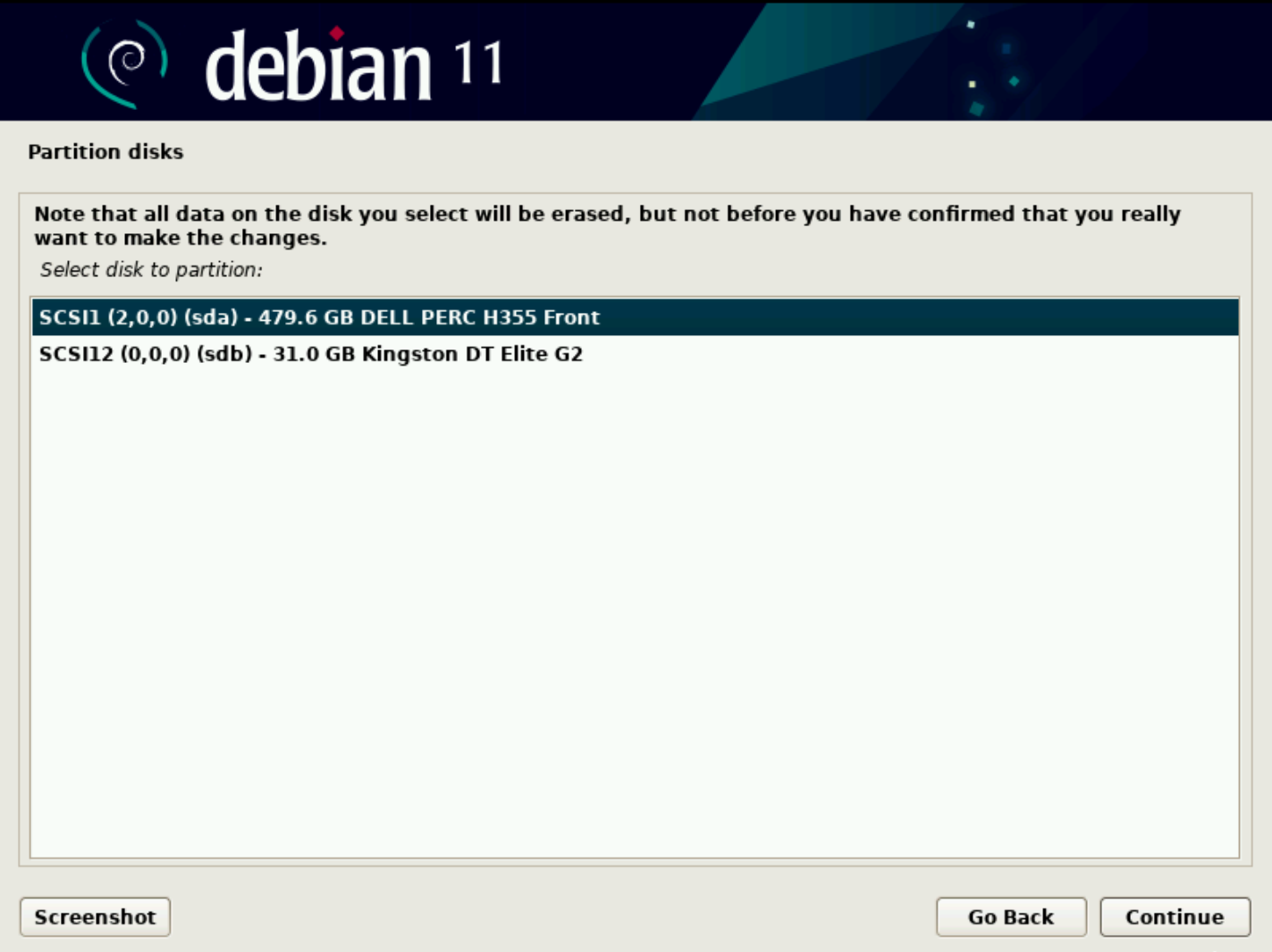](https://docs.junger.audio/uploads/images/gallery/2026-09/scaled-1680-/GOrHL0iPJU4kotIi-install5-png.png) **Select the internal system disk. Do not select the USB installation drive. Applies to both installation methods.****Important -** All existing data on the selected target disk will be erased during installation. Verify the selected disk carefully before continuing.
### 4. Complete the Installation Allow the installer to complete the installation process. [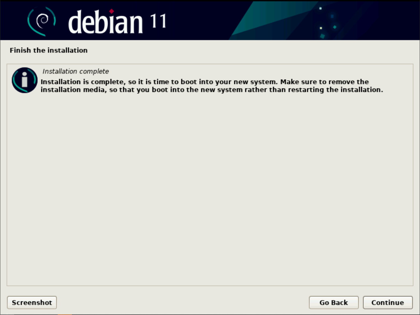](https://docs.junger.audio/uploads/images/gallery/2026-09/scaled-1680-/U5uSmVAZqq8JQYBR-install6-png.png) **Installation complete. Applies to both installation methods.** Before rebooting: - **USB installation:** Remove the USB installation drive. - **iDRAC installation:** Unmap or disconnect the virtual installation media. Restart the server and allow it to boot from the newly installed system disk. Continue with the **Initial Setup** procedure to complete the flexAIserver configuration. # Software Installation Guide HPE ### HPE ProLiant DL360 Gen11 This guide describes the initial hardware configuration and installation of **flexAIserver** on the qualified **HPE ProLiant DL360 Gen11** platform. The server can be configured locally using a VGA monitor and USB keyboard or remotely using **HPE iLO**.**Important -** This guide applies only to the HPE ProLiant DL360 Gen11 server qualified for flexAIserver. Do not apply the server-specific RAID, BIOS, or remote-management instructions to other hardware platforms.
### Prerequisites Before starting, make sure the following are available: - The flexAIserver ISO image. If supplied inside a ZIP archive, extract the ISO before use. - Two internal SSDs installed in the server for the RAID1 system volume. - For local access: a VGA monitor and USB keyboard. - For USB installation: a USB flash drive with sufficient capacity. Its existing contents will be erased. - For remote access: a network connection to the dedicated iLO port and access to the iLO credentials printed on the server top lid.**Warning -** Creating the RAID volume and installing flexAIserver will erase data on the selected internal drives.
--- ### 1. Initial Server Configuration #### Access the Server The server can be configured remotely through **HPE iLO** or locally using a monitor and keyboard. #### Option A – HPE iLO Remote Access 1. Connect a network cable to the port labelled **iLO**. 2. For the initial connection, connect a monitor to the VGA port and power on the server. 3. Note the iLO IP address shown during startup. 4. Open the iLO IP address in a web browser. 5. Log in using **Administrator** as the user name. The initial password is printed on the server top lid. 6. In the iLO interface, open the **Remote Console** from the preview tile. [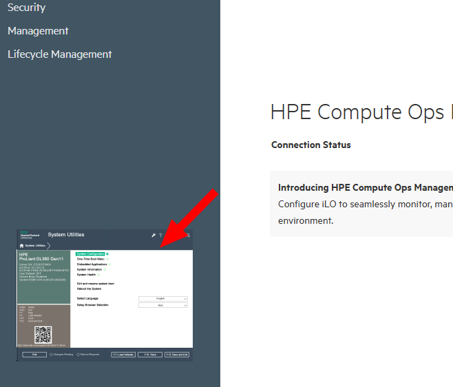](https://docs.junger.audio/uploads/images/gallery/2026-09/scaled-1680-/Q3yhsNJriaDSWakk-screen1-png.png) **Launch the HPE iLO Remote Console from the preview tile.** #### Option B – Local Access 1. Connect a monitor to the VGA port. 2. Connect a USB keyboard. 3. Perform the following configuration steps directly on the local server console. #### Open System Utilities Power on or restart the server. During startup, press **F9** to open **System Utilities**. #### Prepare the SSDs for RAID1 Open: **System Utilities > System Configuration > HPE MR216io Gen11 > Main Menu > Configuration Management > Create Logical Drive** If the SSDs are listed as JBOD drives, select both internal SSDs and confirm the selection so that they can be used for the logical drive. [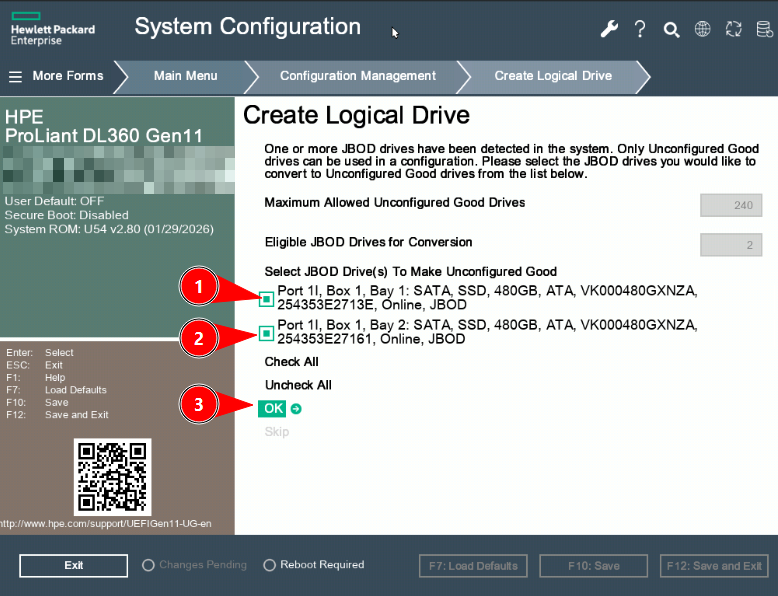](https://docs.junger.audio/uploads/images/gallery/2026-09/scaled-1680-/IxEUCVLIcDxgHyTU-screen2-png.png) **Select both internal SSDs and confirm the selection.** #### Create the RAID1 Logical Drive Set **Select RAID Level** to **RAID1**. Choose **Select Drives** and verify that both internal SSDs are selected. Then select **Save Configuration**. [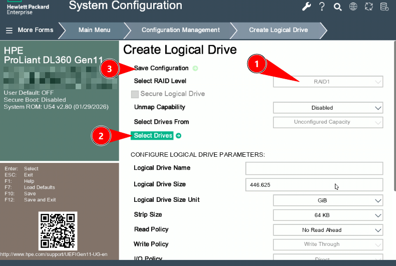](https://docs.junger.audio/uploads/images/gallery/2026-09/scaled-1680-/W9F8Dv6DdO9qnduB-screen3-png.png) **Select RAID1, verify both drives, and save the configuration.** Confirm the configuration. When the logical drive has been created successfully, press **Esc** to return to the previous menu. #### Apply the Low Latency Workload Profile In **System Utilities**, open: **System Configuration > BIOS/Platform Configuration (RBSU) > Workload Profile** Select **Low Latency** and confirm the message. [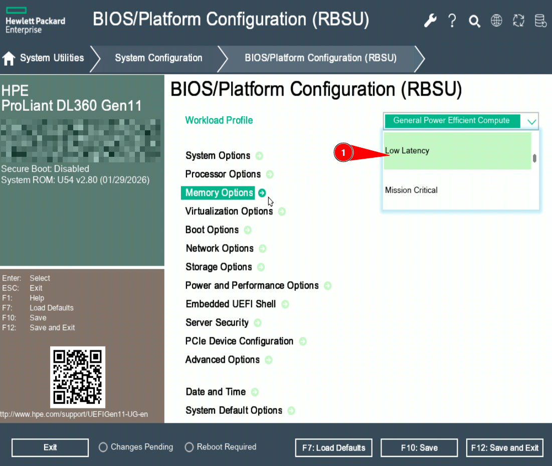](https://docs.junger.audio/uploads/images/gallery/2026-09/scaled-1680-/jkMpomRCaNpfcvBp-screen4-png.png) **Select the Low Latency workload profile.** Press **F12** to save the configuration and exit. The server restarts. #### Change the Workload Profile to Custom During the next startup, press **F9** again and open: **System Utilities > System Configuration > BIOS/Platform Configuration (RBSU) > Workload Profile** Select **Custom**, which is the last entry in the list, and confirm the message. [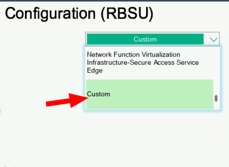](https://docs.junger.audio/uploads/images/gallery/2026-09/scaled-1680-/cak45ZdHBosuQ3kh-screen8-png.png) **Select Custom as the workload profile.** #### Configure Virtualization Options Open **Virtualization Options** and configure the settings as follows: - **Intel(R) Virtualization Technology (Intel VT):** Disabled - **Intel(R) VT-d:** Enabled - **Access Control Service:** Disabled - **SR-IOV:** Disabled [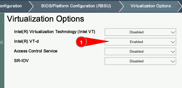](https://docs.junger.audio/uploads/images/gallery/2026-09/scaled-1680-/DZnuLWTHVAs1sJkQ-screen9-png.png) **Enable Intel VT-d and keep the other virtualization options disabled.** Press **F12** to save the configuration and exit. --- ### 2. flexAIserver Software Installation The flexAIserver software can be installed either from a bootable USB drive or remotely through **HPE iLO Virtual Media**. Once the Jünger installation menu appears, the remaining installation procedure is identical for both methods. ### Method A – USB Drive #### Create a Bootable USB Drive Use a suitable image-writing tool such as **balenaEtcher** to write the flexAIserver ISO image to the USB drive: [https://www.balena.io/etcher/](https://www.balena.io/etcher/) The USB drive will be erased. 1. Insert the USB drive into a front USB port. 2. Connect a keyboard. 3. Power on or restart the server. 4. During startup, press **F11** to open the Boot Menu. 5. Select the UEFI entry corresponding to the USB installation drive. [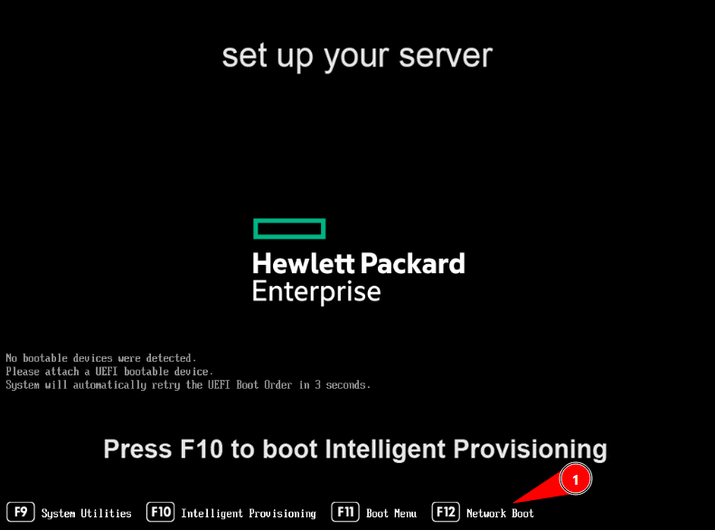](https://docs.junger.audio/uploads/images/gallery/2026-09/scaled-1680-/mljiLY9X4Dvchyos-screen6-png.png) **Press F11 during startup and select the USB installation media.** Continue with **Installation Procedure – Applies to Both Methods** below. ### Method B – HPE iLO Virtual Media #### Map the ISO as Virtual Media Make sure the server is powered off. If it is currently running, shut it down using the iLO power controls or the physical front-panel power button. Launch the **Remote Console** as described above. In the Remote Console: 1. Select **Virtual Media**. 2. Select **CD/DVD**. 3. Select \**Local *.iso file**. 4. Select the flexAIserver ISO image. [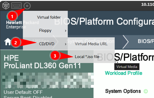](https://docs.junger.audio/uploads/images/gallery/2026-09/scaled-1680-/UPTmYNOziZWbEkMl-screen5-png.png) **Open Virtual Media, select CD/DVD, and map the flexAIserver ISO image.** #### Boot from the Virtual Media Keep the **Remote Console** open during installation. Closing it may disconnect the virtual installation media. Power on the server using **Power > Momentary Press** in iLO. Wait for the Jünger installation menu to appear. If the server does not boot from the virtual media automatically, press **F11** during startup, open the Boot Menu, and select the virtual CD/DVD or corresponding virtual-media source. --- ### Installation Procedure – Applies to Both Methods The following steps are identical whether the installation media is connected by USB or through HPE iLO. #### Start the flexAIserver Installer When the Jünger installation menu appears on the local display or in the Remote Console, select the available installation option, such as **Graphical Install** or **Install**, and press **Enter**. [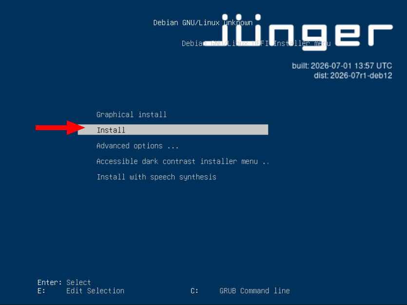](https://docs.junger.audio/uploads/images/gallery/2026-09/scaled-1680-/m4spXmQD2DUtAkm1-screen7-png.png) **Select the installation option and press Enter.****Note -** The Debian version and build information shown in the following example screenshots may differ from the delivered flexAIserver ISO. The installation procedure remains the same.
#### Set the Hostname When prompted, enter the hostname for the flexAIserver. For example: `flexAIserver-00119` The final digits of the device serial number may be used, or another hostname can be chosen according to the naming convention of the network environment. [](https://docs.junger.audio/uploads/images/gallery/2026-09/scaled-1680-/Ef4PdszcTJ6btFri-install4-png.png) **Enter the hostname for the flexAIserver.** #### Select the Target Disk Select the internal **RAID1 logical volume** created during the initial server configuration. Do not select the USB installation drive.**Important -** The device names and capacities shown on the HPE server may differ from the generic example below. Identify the internal RAID1 logical volume by its capacity and controller information before continuing.
[](https://docs.junger.audio/uploads/images/gallery/2026-09/scaled-1680-/GOrHL0iPJU4kotIi-install5-png.png) **Select the internal RAID1 logical volume, not the USB installation drive.****Warning -** All existing data on the selected target disk will be erased during installation.
#### Finish the Installation When the installer reports that the installation is complete: - **USB installation:** Remove the USB drive before continuing. - **HPE iLO installation:** Unmount or disconnect the virtual CD/DVD image before continuing. Keep the Remote Console open until the reboot has completed. Select **Continue** to reboot into the newly installed system. [](https://docs.junger.audio/uploads/images/gallery/2026-09/scaled-1680-/U5uSmVAZqq8JQYBR-install6-png.png) **Installation complete – remove the physical or virtual installation media before rebooting.** After the server has booted, continue with the **flexAIserver Initial Setup**. # Safety Information**Critical information -** Please read the following safety information carefully before installing, operating, or servicing the flexAIserver hardware.
### Electrical Safety - Connect the server only to mains outlets that provide a protective earth connection. - Make sure that the mains power cords remain accessible so that the server can be disconnected from mains power when required. - Servers equipped with redundant power supplies use separate mains connections for each power supply. All connected power cords must be disconnected to completely remove mains power from the server. - Use only power cords that are suitable for the server hardware and approved for use in the country or region of installation. - Do not expose the server to dripping or splashing water and do not place containers filled with liquid on or directly above the unit.**Note -** The exact mains connections, power controls, and electrical specifications depend on the installed server hardware. Refer to the safety and installation documentation supplied by the server manufacturer.
### Service Safety Service work must only be carried out by suitably qualified personnel. Before opening or servicing the server: 1. Shut down the operating system when possible. 2. Switch off the server. 3. Disconnect all mains power cords. 4. Make sure that the power cords cannot be reconnected accidentally while service work is in progress. Do not perform internal service work while the server is connected to mains power unless the procedure is explicitly specified by the server manufacturer and is carried out by suitably qualified personnel. ### Installation and Operation - Install the server in a standard 19-inch equipment rack using the rack-mounting hardware specified for the server model. - Make sure that the server is adequately supported and securely installed in the rack. - The server is actively cooled. Keep all ventilation openings clear and maintain the airflow specified by the server manufacturer. - Additional empty rack units above or below the server are normally not required unless specified by the server manufacturer or by the cooling concept of the installation. - Do not operate the server with covers, panels, or other safety components removed. - If the server, power cords, connectors, or other components appear damaged, disconnect the server from mains power and have it inspected by qualified service personnel before further use. ### Internal Battery Server hardware may contain one or more internal lithium batteries.**Warning -** Internal batteries must only be replaced with the type specified by the server manufacturer. Incorrect replacement or installation may present a risk of fire or explosion. Follow the manufacturer's instructions for replacement and disposal.
### Manufacturer Safety Information The flexAIserver software may be supplied on different qualified server platforms. Hardware-specific safety instructions, rack-mounting requirements, environmental limits, servicing procedures, and regulatory information are provided by the respective server manufacturer.**Important -** Always follow the safety and installation documentation supplied with the installed server hardware. Where hardware-specific instructions differ from the general information on this page, the server manufacturer's instructions take precedence.
# flexAIserver - Technical Data # tieLight portal PCIe ##### tieLight Portal PCIe – tieLight and MADI I/O Card (O\_Serv\_AI\_MADI\_TIE\_a) The tieLight Portal PCIe card provides optical tieLight and MADI audio I/O together with an external synchronization input. #### Standards - MADI interface compliant with **AES10-2008** - Synchronization interface compliant with **AES11-2009** and the applicable audio and video synchronization standards #### Audio - 24-bit audio - Transparent transport of PCM and compressed audio - Supported sample rates: - 44.1 kHz - 48 kHz - 88.2 kHz - 96 kHz - 88.2 kHz and 96 kHz use short-frame MADI operation**Important -** Not all sample rates may be supported by the host system. Refer to the specifications of the respective flexAI system.
#### Optical Input - Connector: LC, according to IEC 61754-20 - Audio channels: - 64 / 56 channels at 44.1 and 48 kHz - 32 / 28 channels at 88.2 and 96 kHz - Single-mode center wavelength: - 1310 nm typical - 1270 to 1360 nm - Multimode center wavelength: - 1310 nm typical - 1270 to 1360 nm ##### Optical Input Power| Optical Module | Fiber Type | Input Optical Power |
|---|---|---|
| O\_DAP\_MO\_MM\_a | OM2 multimode, 50/125 µm | -31 to -8 dBm |
| O\_DAP\_MO\_SM\_a | Single-mode | -23 to -8 dBm |
| Optical Module | Fiber Type | Maximum Cable Length |
|---|---|---|
| O\_DAP\_MO\_MM\_a | OM2 multimode | 1.5 km |
| O\_DAP\_MO\_SM\_a | Single-mode | 2 km |