Interfaces
- Audio over IP - Setup
- Audio over IP - New Stream Defaults
- Audio over IP - Receivers
- Audio over IP - Senders
- tieLight / MADI
- AES3
- Analog
- Headphone
- NDI
- Dante
Audio over IP - Setup
The AoIP section under Interfaces provides the configuration and status information for Audio over IP operation.
Important - IGMP Snooping must be enabled on all switch ports connected to flexAI systems. Otherwise, forwarded multicast traffic may stress the connected system.
Expand AoIP in the Interfaces menu and select Setup.
Note - Some AoIP parameters are only visible when **Show Expert Settings** is enabled. Enable this option to display all parameters described in this section.
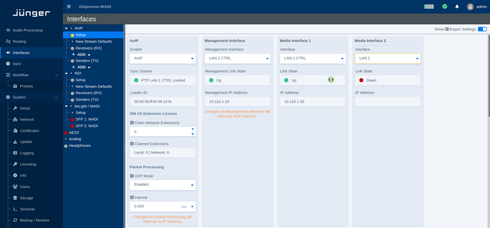
The page is divided into several sections for general AoIP configuration, network interfaces, synchronization, Livewire, NMOS, receiver settings, and sender settings.
Changes to some low-level AoIP settings may temporarily interrupt active AoIP streams. Where this applies, a corresponding message is shown on the page.
AoIP
This section controls the general AoIP operation and shows the current synchronization status.
| Parameter | Values | Default | Description |
|---|---|---|---|
| Enable | Available AoIP modes / Disabled | - | Enables or disables Audio over IP operation. |
| Sync Source | Status | - | Shows the synchronization source currently used for AoIP and whether the clock is locked. |
| Leader ID | Status | - | Shows the identifier of the PTP Leader Clock currently providing synchronization on the network. |
Channel Extension License
Additional licensed AoIP channel capacity can be made available locally or through network licensing.
| Parameter | Values | Default | Description |
|---|---|---|---|
| Claim Network Extensions | Number of extensions | - | Defines how many available channel extension licenses should be claimed from the network. |
| Claimed Extensions | Status | - | Shows the number of channel extensions currently claimed from local and network license sources. |
Packet Processing
These parameters control low-level packet processing for AoIP.
XDP provides highly efficient packet processing close to the network interface, reducing the CPU overhead associated with AoIP traffic. This makes it possible to handle higher packet rates and very small packet times more efficiently.
| Parameter | Values | Default | Description |
|---|---|---|---|
| XDP Mode | Enabled / Disabled | - | Enables or disables XDP-based packet processing for AoIP. |
| Interval | Supported intervals | - | Defines the packet-processing interval. Incoming packets are collected for this period and then passed on for processing as a group. |
Changing packet-processing settings may interrupt active AoIP streams.
Management Interface
The Management Interface is used for AoIP control and management communication.
The **Management Interface** is used for AoIP control and management traffic, including protocols such as **NMOS**. Selecting the correct Management Interface is therefore important, as these services may be restricted to this interface.
| Parameter | Values | Default | Description |
|---|---|---|---|
| Management Interface | Available network interfaces | - | Selects the network interface used for AoIP management communication. |
| Management Link State | Status | - | Shows whether the selected management interface has an active network link. |
| Management IP Address | Status | - | Shows the IP address assigned to the selected management interface. |
Changing the Management Interface may interrupt active AoIP streams.
Media Interfaces
Media Interfaces carry the AoIP media traffic. Up to four Media Interfaces can be configured, depending on the system and its available network interfaces.
All Media Interface sections use the same parameters.
| Parameter | Values | Default | Description |
|---|---|---|---|
| Interface | Available network interfaces / Disabled | - | Selects the network interface used for AoIP media traffic. Select **Disabled** if the Media Interface is not required. |
| Link State | Status | - | Shows the current physical link state of the selected network interface. |
| IP Address | Status | - | Shows the IP address assigned to the selected Media Interface. |
Livewire
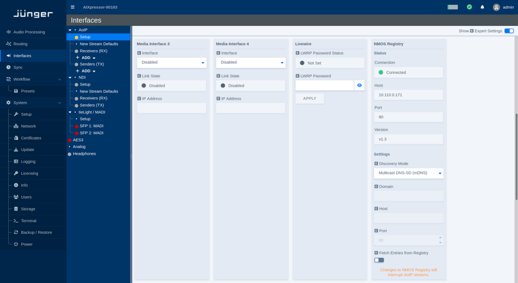
The Livewire section provides the password used for Livewire Routing Protocol (LWRP) access.
| Parameter | Values | Default | Description |
|---|---|---|---|
| LWRP Password Status | Status | - | Indicates whether an LWRP password has been configured. |
| LWRP Password | Password | - | Sets the password used for LWRP access. Use the visibility icon to show or hide the entered password. |
| Apply | Button | - | Applies the entered LWRP password. |
NMOS Registry
The NMOS Registry section shows the current NMOS registry connection and provides the corresponding discovery settings.
Status
| Parameter | Values | Default | Description |
|---|---|---|---|
| Connection | Status | - | Shows whether the flexAI system is currently connected to an NMOS Registry. |
| Host | Status | - | Shows the address of the currently used NMOS Registry. |
| Port | Status | - | Shows the port used for the current registry connection. |
| Version | Status | - | Shows the NMOS API version used for the registry connection. |
Settings
| Parameter | Values | Default | Description |
|---|---|---|---|
| Discovery Mode | Available discovery modes | - | Selects how the NMOS Registry is discovered. |
| Domain | Domain name | - | Defines the DNS domain used for registry discovery when required by the selected Discovery Mode. |
| Host | Host name or IP address | - | Defines the NMOS Registry host when manual registry configuration is used. |
| Port | Port number | - | Defines the port of the manually configured NMOS Registry. |
| Fetch Entries from Registry | On / Off | - | Enables retrieval of available entries from the connected NMOS Registry. |
Changing the NMOS Registry configuration may interrupt active AoIP streams.
Receiver
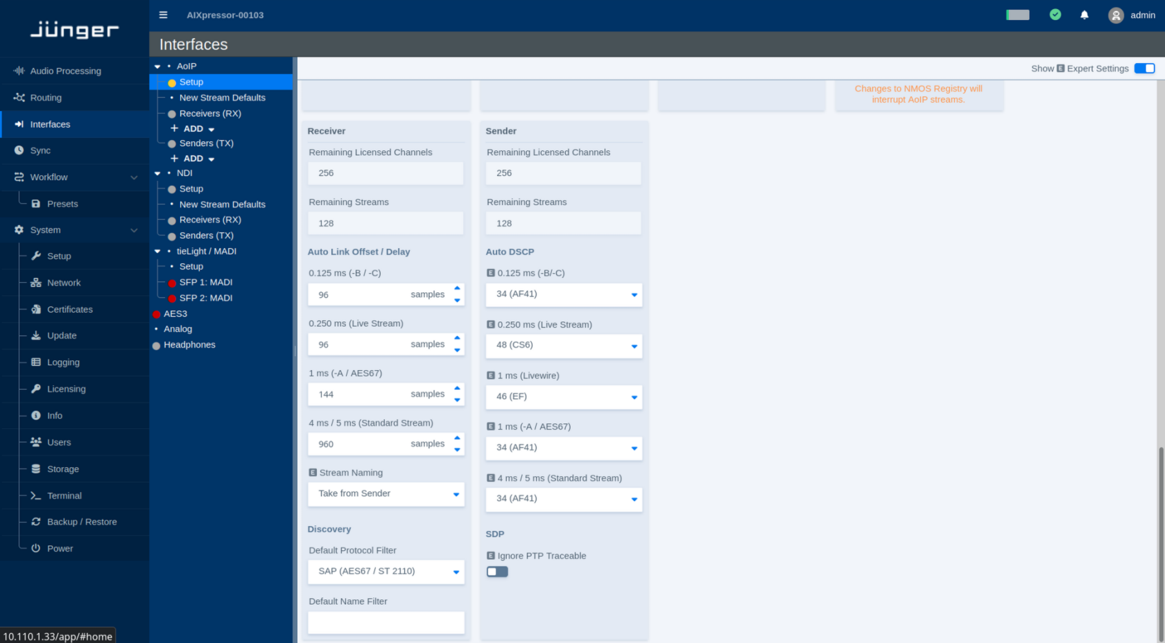
The Receiver section shows the remaining receiver capacity and defines default behavior for automatically connected streams and stream discovery.
Capacity
| Parameter | Values | Default | Description |
|---|---|---|---|
| Remaining Licensed Channels | Status | - | Shows the number of licensed receive channels that are currently still available. |
| Remaining Streams | Status | - | Shows the number of additional receiver streams that can currently be created. |
Auto Link Offset / Delay
The Auto Link settings define the receiver delay used when streams are connected automatically. Separate values are provided for the supported stream and packet-time classes.
Auto Link Offset defines the fixed receive/playout delay that is automatically applied when a stream is linked. It provides additional time for network packets to arrive before they are presented to the audio engine, improving tolerance to network jitter and late packets.
A separate offset can be configured for each packet-time class. Once applied, the delay remains constant for streams of that type, so the additional latency is deterministic rather than varying with network conditions.
| Parameter | Values | Default | Description |
|---|---|---|---|
| 0.125 ms (-B / -C) | Delay in samples | - | Defines the Auto Link offset/delay for streams using a 0.125 ms packet time. |
| 0.250 ms (Live Stream) | Delay in samples | - | Defines the Auto Link offset/delay for Live Streams using a 0.250 ms packet time. |
| 1 ms (-A / AES67) | Delay in samples | - | Defines the Auto Link offset/delay for streams using a 1 ms packet time, including AES67 streams. |
| 4 ms / 5 ms (Standard Stream) | Delay in samples | - | Defines the Auto Link offset/delay for Standard Streams using the corresponding packet-time class. |
Higher delay values provide additional buffering at the receiver but also increase the end-to-end audio latency.
Stream Naming
| Parameter | Values | Default | Description |
|---|---|---|---|
| Stream Naming | Available naming modes | - | Defines how automatically connected receiver streams are named. **Take from Sender** uses the name provided by the sending device. |
Discovery
| Parameter | Values | Default | Description |
|---|---|---|---|
| Default Protocol Filter | Available discovery protocols | - | Selects the protocol filter initially applied when discovering streams. Depending on the system configuration, this may include Livewire, SAP for AES67/ST 2110, or NMOS. |
| Default Name Filter | Text | - | Defines an optional name filter applied when displaying discovered streams. Leave the field empty to show streams regardless of their name. |
Sender
The Sender section shows the remaining sender capacity and defines default network parameters for transmitted streams.
Capacity
| Parameter | Values | Default | Description |
|---|---|---|---|
| Remaining Licensed Channels | Status | - | Shows the number of licensed transmit channels that are currently still available. |
| Remaining Streams | Status | - | Shows the number of additional sender streams that can currently be created. |
Auto DSCP
Auto DSCP defines the Differentiated Services Code Point (DSCP) automatically assigned to transmitted AoIP packets for each supported stream type.
| Parameter | Values | Default | Description |
|---|---|---|---|
| 0.125 ms (-B / -C) | DSCP value / class | - | Defines the DSCP marking used for streams with a 0.125 ms packet time. |
| 0.250 ms (Live Stream) | DSCP value / class | - | Defines the DSCP marking used for Live Streams with a 0.250 ms packet time. |
| 1 ms (Livewire) | DSCP value / class | - | Defines the DSCP marking used for Livewire streams with a 1 ms packet time. |
| 1 ms (-A / AES67) | DSCP value / class | - | Defines the DSCP marking used for 1 ms AES67 streams. |
| 4 ms / 5 ms (Standard Stream) | DSCP value / class | - | Defines the DSCP marking used for Standard Streams with the corresponding packet-time class. |
**DSCP (Differentiated Services Code Point)** is a field in the IP header used to classify network traffic for Quality of Service (QoS). Network switches and routers can use this value to prioritize time-critical AoIP packets over less critical traffic.
**Auto DSCP** automatically assigns the appropriate DSCP value according to the selected stream type and packet time. This helps ensure that streams with higher timing requirements receive the intended network priority without having to configure the DSCP value manually.
SDP
| Parameter | Values | Default | Description |
|---|---|---|---|
| Ignore PTP Traceable | On / Off | - | Ignores PTP traceability information when evaluating SDP data. This can be relevant for streams that use absolute timing information referenced to the Unix epoch beginning on January 1, 1970. |
Audio over IP - New Stream Defaults
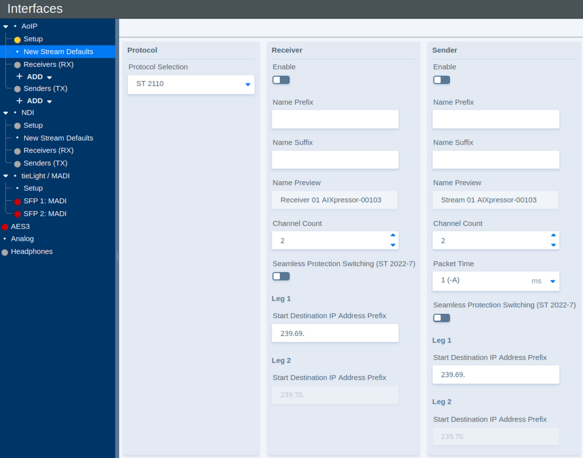
The New Stream Defaults page defines the initial settings used when new AoIP receiver or sender streams are created.
Changing these settings affects newly created streams only. Existing receivers and senders are not modified.
Select the protocol under Protocol Selection to configure the corresponding defaults. The available parameters may vary depending on the selected protocol.
Protocol
| Parameter | Values | Default | Description |
|---|---|---|---|
| Protocol Selection | Available AoIP protocols | - | Selects the AoIP protocol for which the new-stream defaults are being configured. The available Receiver and Sender parameters may change with the selected protocol. |
SMPTE ST2110 and AES67
Receiver Defaults
These parameters define the initial configuration of newly created AoIP receivers.
| Parameter | Values | Default | Description |
|---|---|---|---|
| Enable | On / Off | - | Defines whether newly created receivers are enabled by default. |
| Name Prefix | Text | - | Defines an optional prefix added to the name of newly created receivers. |
| Name Suffix | Text | - | Defines an optional suffix added to the name of newly created receivers. |
| Name Preview | Status | - | Shows a preview of the resulting receiver name. |
| Channel Count | Supported channel counts | - | Defines the default number of audio channels for a newly created receiver. |
| Seamless Protection Switching (ST 2022-7) | On / Off | - | Enables SMPTE ST 2022-7 seamless protection switching for newly created receivers. When enabled, redundant stream legs can be received over separate network paths. |
| Start Destination IP Address Prefix – Leg 1 | Multicast IP prefix | - | Defines the starting multicast destination address prefix used for automatic address assignment. When multiple streams are created, the destination addresses are incremented automatically. |
| Start Destination IP Address Prefix – Leg 2 | Multicast IP prefix | - | Defines the starting multicast destination address prefix used for the redundant second stream leg. When multiple streams are created, the destination addresses are incremented automatically. |
Sender Defaults
These parameters define the initial configuration of newly created AoIP senders.
| Parameter | Values | Default | Description |
|---|---|---|---|
| Enable | On / Off | - | Defines whether newly created senders are enabled by default. |
| Name Prefix | Text | - | Defines an optional prefix added to the name of newly created senders. |
| Name Suffix | Text | - | Defines an optional suffix added to the name of newly created senders. |
| Name Preview | Status | - | Shows a preview of the resulting sender name. |
| Channel Count | Supported channel counts | - | Defines the default number of audio channels for a newly created sender. |
| Packet Time | Supported packet times | - | Defines the packet time used for newly created sender streams. Shorter packet times reduce transport latency but increase the packet rate and processing load. |
| Seamless Protection Switching (ST 2022-7) | On / Off | - | Enables SMPTE ST 2022-7 seamless protection switching for newly created senders. When enabled, two equivalent stream legs can be transmitted over separate network paths. |
| Start Destination IP Address Prefix – Leg 1 | Multicast IP prefix | - | Defines the starting multicast destination address prefix used for automatic address assignment. When multiple streams are created, the destination addresses are incremented automatically. |
| Start Destination IP Address Prefix – Leg 2 | Multicast IP prefix | - | Defines the starting multicast destination address prefix used for the redundant second stream leg. When multiple streams are created, the destination addresses are incremented automatically. |
Additional Settings
Additional parameters are available when Show Expert Settings is enabled.
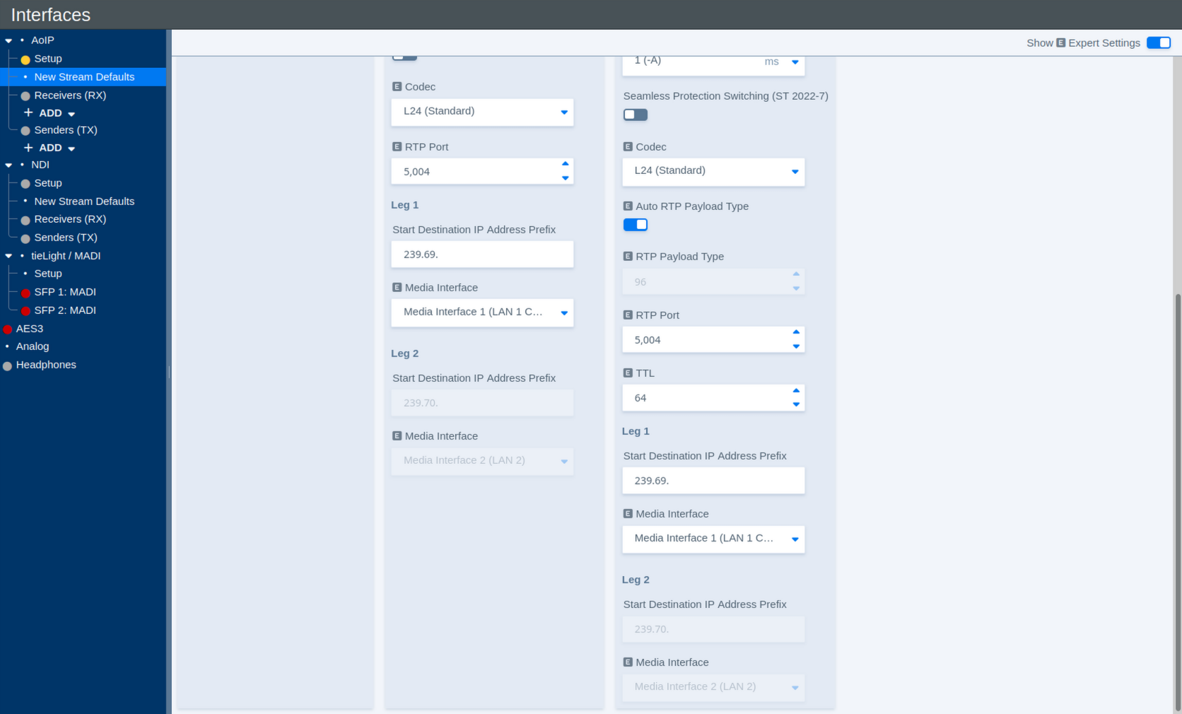
The Expert View adds further Receiver and Sender defaults.
Receiver – Additional Settings
| Parameter | Values | Default | Description |
|---|---|---|---|
| Codec | Available codecs | - | Defines the default audio codec or sample format used for newly created receivers. |
| RTP Port | Port number | - | Defines the RTP port used for newly created receiver streams. |
| Media Interface – Leg 1 | Available Media Interfaces | - | Selects the Media Interface used for the first stream leg. |
| Media Interface – Leg 2 | Available Media Interfaces | - | Selects the Media Interface used for the redundant second stream leg when ST 2022-7 is enabled. |
Sender – Additional Settings
| Parameter | Values | Default | Description |
|---|---|---|---|
| Codec | Available codecs | - | Defines the audio codec or sample format used for newly created sender streams. |
| Auto RTP Payload Type | On / Off | - | Automatically assigns a suitable RTP payload type to newly created streams. Disable this option to specify the payload type manually. |
| RTP Payload Type | RTP payload type | - | Defines the RTP payload type when automatic assignment is disabled. |
| RTP Port | Port number | - | Defines the RTP port used for newly created sender streams. |
| TTL | Number of network hops | - | Defines the IP multicast Time To Live (TTL). The value limits how many routed network hops a multicast stream can traverse. |
| Media Interface – Leg 1 | Available Media Interfaces | - | Selects the Media Interface used to transmit the first stream leg. |
| Media Interface – Leg 2 | Available Media Interfaces | - | Selects the Media Interface used to transmit the redundant second stream leg when ST 2022-7 is enabled. |
Livewire
When Livewire is selected under Protocol Selection, some of the New Stream Defaults differ from those available for ST 2110.
Instead of assigning multicast destination addresses directly, Livewire uses Livewire Channel numbers. These channel numbers determine the corresponding multicast destination used by the Livewire stream.
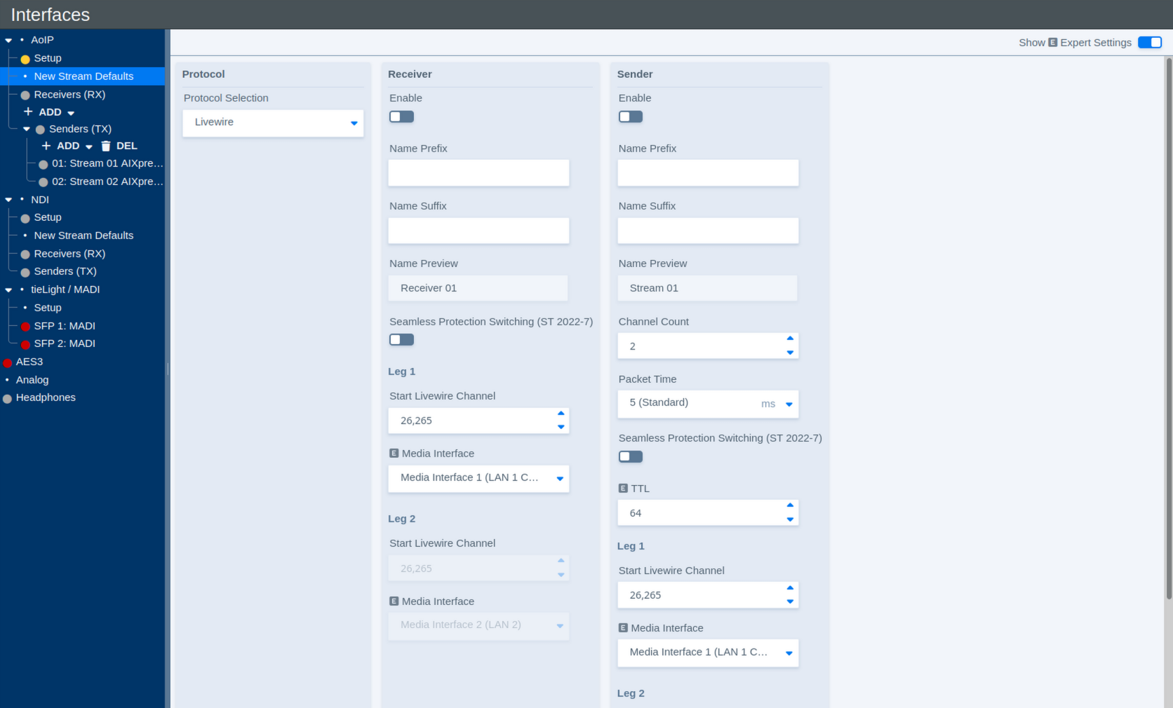
Receiver Defaults
| Parameter | Values | Default | Description |
|---|---|---|---|
| Enable | On / Off | - | Defines whether newly created Livewire receivers are enabled by default. |
| Name Prefix | Text | - | Defines an optional prefix added to the name of newly created receivers. |
| Name Suffix | Text | - | Defines an optional suffix added to the name of newly created receivers. |
| Name Preview | Status | - | Shows a preview of the resulting receiver name. |
| Seamless Protection Switching (ST 2022-7) | On / Off | - | Enables SMPTE ST 2022-7 seamless protection switching for newly created receivers. |
| Start Livewire Channel – Leg 1 | Livewire channel number | - | Defines the first Livewire Channel number used for automatically created receiver streams. When multiple streams are created, the channel number is incremented automatically. |
| Media Interface – Leg 1 | Available Media Interfaces | - | Selects the Media Interface used for the first stream leg. |
| Start Livewire Channel – Leg 2 | Livewire channel number | - | Defines the starting Livewire Channel number for the redundant second stream leg. When multiple streams are created, the channel number is incremented automatically. |
| Media Interface – Leg 2 | Available Media Interfaces | - | Selects the Media Interface used for the redundant second stream leg when ST 2022-7 is enabled. |
Sender Defaults
| Parameter | Values | Default | Description |
|---|---|---|---|
| Enable | On / Off | - | Defines whether newly created Livewire senders are enabled by default. |
| Name Prefix | Text | - | Defines an optional prefix added to the name of newly created senders. |
| Name Suffix | Text | - | Defines an optional suffix added to the name of newly created senders. |
| Name Preview | Status | - | Shows a preview of the resulting sender name. |
| Channel Count | Supported channel counts | - | Defines the default number of audio channels for a newly created Livewire sender. |
| Packet Time | Supported packet times | - | Defines the packet time used for newly created Livewire streams. Shorter packet times reduce transport latency but increase the packet rate and processing load. |
| Seamless Protection Switching (ST 2022-7) | On / Off | - | Enables SMPTE ST 2022-7 seamless protection switching for newly created senders. |
| TTL | Number of network hops | - | Defines the IP multicast Time To Live (TTL). The value limits how many routed network hops a multicast stream can traverse. |
| Start Livewire Channel – Leg 1 | Livewire channel number | - | Defines the first Livewire Channel number used for automatically created sender streams. When multiple streams are created, the channel number is incremented automatically. |
| Media Interface – Leg 1 | Available Media Interfaces | - | Selects the Media Interface used to transmit the first stream leg. |
| Start Livewire Channel – Leg 2 | Livewire channel number | - | Defines the starting Livewire Channel number for the redundant second stream leg. When multiple streams are created, the channel number is incremented automatically. |
| Media Interface – Leg 2 | Available Media Interfaces | - | Selects the Media Interface used to transmit the redundant second stream leg when ST 2022-7 is enabled. |
Audio over IP - Receivers
Receivers
The Receivers (RX) section under AoIP contains the receive streams configured on the flexAI system.
Use ADD to create a new receiver. Existing receivers are listed below Receivers (RX) and can be selected individually for configuration. Use DEL to remove selected receivers.
Some receiver parameters are only visible when Show Expert Settings is enabled.
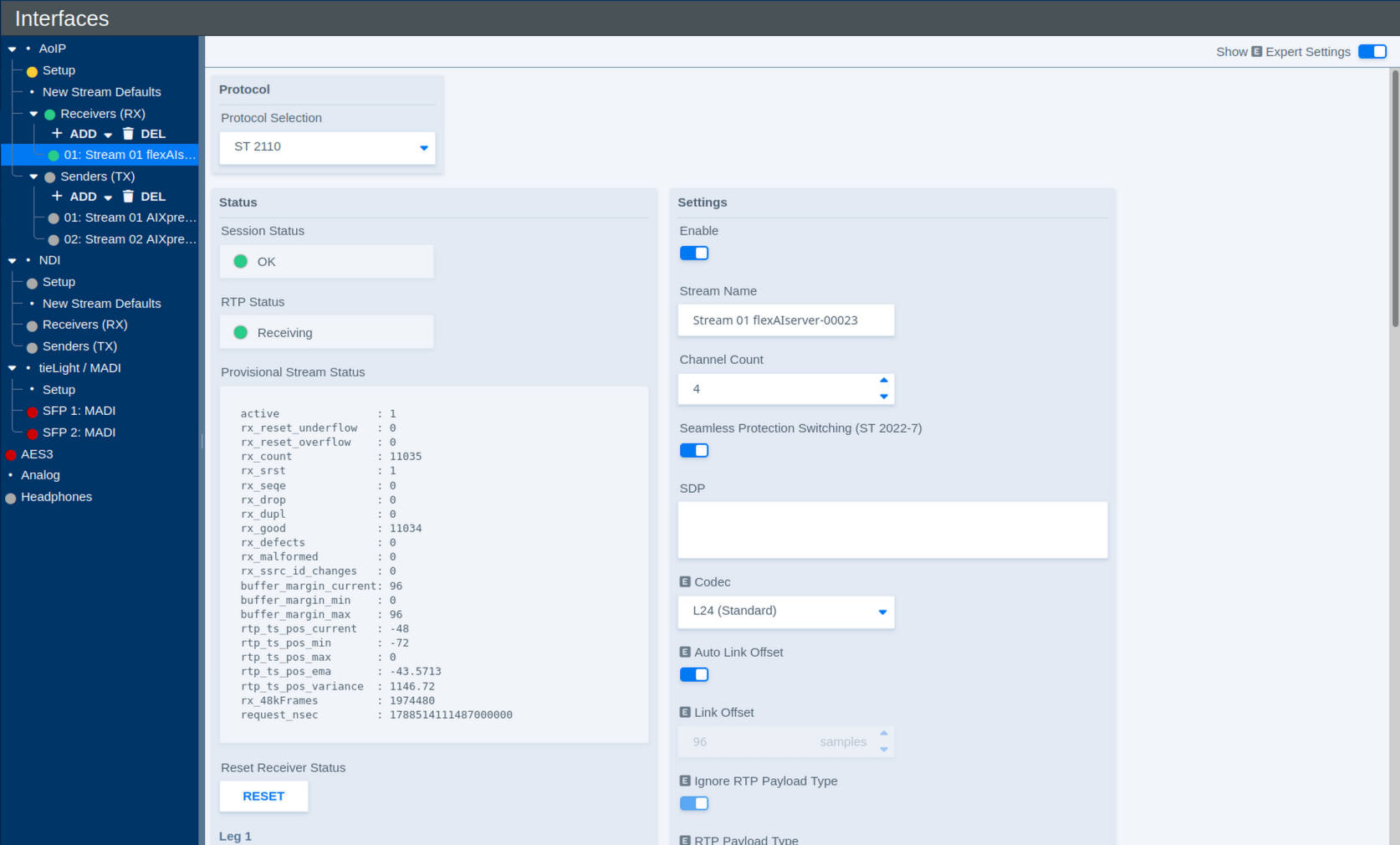
Protocol
| Parameter | Values | Default | Description |
|---|---|---|---|
| Protocol Selection | Available AoIP protocols | - | Selects the protocol used by the receiver. The available settings may change depending on the selected protocol. |
Status
The Status section shows the current operating state of the receiver and its stream legs.
| Parameter | Values | Default | Description |
|---|---|---|---|
| Session Status | Status | - | Shows the overall status of the receive session. |
| RTP Status | Status | - | Shows whether RTP packets are currently being received. |
| Provisional Stream Status | Diagnostic information | - | Provides detailed receiver statistics and diagnostic information about the incoming RTP stream. |
| Reset Receiver Status | Button | - | Resets the displayed receiver status and diagnostic counters. |
| RTP Status – Leg 1 | Status | - | Shows the receive status of both stream legs combined. |
| RTP Status – Leg 2 | Status | - | Currently not used |
The Provisional Stream Status is primarily intended for diagnostics and troubleshooting. For normal operation, the Session and RTP status indicators provide the most relevant overview.
Settings
| Parameter | Values | Default | Description |
|---|---|---|---|
| Enable | On / Off | - | Enables or disables the receiver. |
| Stream Name | Text | - | Defines the name used to identify the receiver within the flexAI system. |
| Channel Count | Supported channel counts | - | Defines the number of audio channels carried by the receive stream. |
| Seamless Protection Switching (ST 2022-7) | On / Off | - | Enables SMPTE ST 2022-7 seamless protection switching. When enabled, two redundant stream legs can be received over separate network paths. |
| SDP | SDP data | - | Defines the Session Description Protocol information for the incoming stream. The original SDP provided by the sender can be pasted directly into this field. Alternatively, SDP information can be obtained from a discovered stream. |
| Codec | Available codecs | - | Defines the expected audio codec or sample format of the incoming stream. |
| Auto Link Offset | On / Off | - | Automatically applies the Link Offset configured for the corresponding stream type and packet time on the AoIP Setup page. |
| Link Offset | Delay in samples | - | Defines the fixed receive/playout delay when Auto Link Offset is disabled. The delay remains constant for the stream, providing deterministic latency. |
| Ignore RTP Payload Type | On / Off | - | Defines whether the configured RTP Payload Type is ignored when receiving the stream. |
| RTP Payload Type | RTP payload type | - | Defines the expected RTP payload type when payload-type checking is used. |
| RTP Port | Port number | - | Defines the UDP port on which the RTP stream is received. |
Pasting the sender's original SDP is often the simplest way to configure a receiver manually, as it transfers the relevant stream parameters in a single step.
Stream Legs
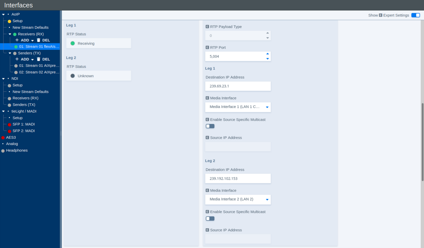
Each receiver can use up to two stream legs. Leg 1 carries the primary stream. Leg 2 is used for redundant reception when ST 2022-7 is enabled.
The following parameters are available for each leg:
| Parameter | Values | Default | Description |
|---|---|---|---|
| Destination IP Address | Multicast IP address | - | Defines the multicast destination address from which the receiver joins the stream. |
| Media Interface | Available Media Interfaces | - | Selects the Media Interface used to receive this stream leg. |
| Enable Source Specific Multicast | On / Off | - | Enables Source-Specific Multicast (SSM) for this stream leg. |
| Source IP Address | IP address | - | Defines the expected source address when Source-Specific Multicast is enabled. |
Each receiver can be assigned individually to one of the available Media Interfaces. This allows different receivers, and, with ST 2022-7, individual stream legs, to use separate physical AoIP networks.
In combination with the internal audio routing, flexAI can also transfer audio between otherwise independent AoIP networks: audio received through one Media Interface can be routed internally and transmitted again through a sender assigned to another Media Interface. This operates at the audio level rather than as a network bridge.
With Source-Specific Multicast (SSM) enabled, the receiver joins the multicast stream from the specified source address rather than accepting traffic for the multicast group from any source.
Stream Discovery
The Discovery section can be used to find available AoIP streams on the network and apply their parameters to the selected receiver.
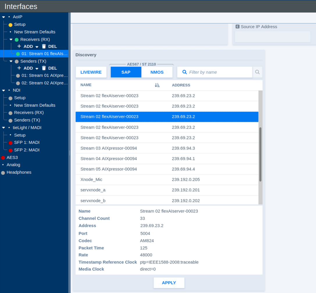
Available discovery methods include:
- Livewire
- SAP for AES67 / ST 2110
- NMOS
Use the protocol buttons to select the desired discovery method. The Filter by name field can be used to narrow the list of discovered streams.
Select a stream to display the information advertised by the sender. Depending on the protocol, this may include information such as:
- Name
- Channel Count
- Destination Address
- RTP Port
- Codec
- Packet Time
- Sample Rate
- Timestamp Reference Clock
- Media Clock
Click Apply to connect the selected stream with the current receiver.
This provides a convenient alternative to entering the receiver parameters manually and helps ensure that the receiver settings match those advertised by the sender.
Livewire Receiver Settings
When Livewire is selected under Protocol Selection, some receiver parameters differ from those used for ST 2110.
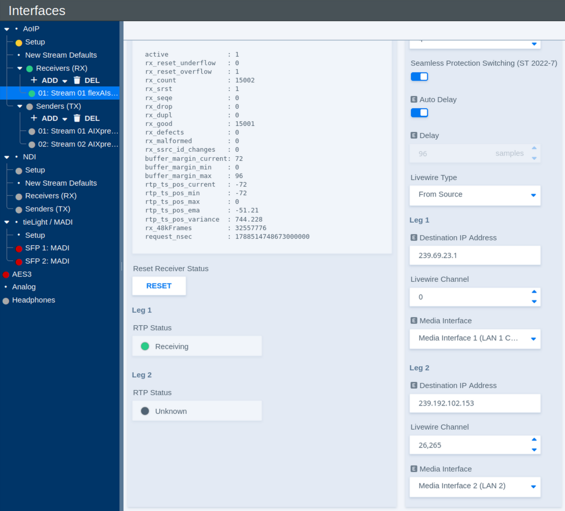
| Parameter | Values | Default | Description |
|---|---|---|---|
| Auto Delay | On / Off | - | Automatically applies the receive delay configured for the corresponding Livewire stream type on the AoIP Setup page. |
| Delay | Delay in samples | - | Defines the fixed receive/playout delay when Auto Delay is disabled. The configured delay remains constant, providing deterministic latency. |
| Livewire Type | Available Livewire types | - | Defines how the Livewire stream is addressed. To Source uses the Livewire channel information associated with the source stream. |
| Destination IP Address – Leg 1 | Multicast IP address | - | Shows or defines the multicast destination address used for the first Livewire stream leg. |
| Livewire Channel – Leg 1 | Livewire channel number | - | Defines the Livewire Channel used for the first stream leg. The Livewire Channel identifies the corresponding stream within the Livewire network. |
| Media Interface – Leg 1 | Available Media Interfaces | - | Selects the Media Interface used to receive the first stream leg. |
| Destination IP Address – Leg 2 | Multicast IP address | - | Shows or defines the multicast destination address used for the redundant second stream leg. |
| Livewire Channel – Leg 2 | Livewire channel number | - | Defines the Livewire Channel used for the redundant second stream leg. |
| Media Interface – Leg 2 | Available Media Interfaces | - | Selects the Media Interface used to receive the redundant second stream leg when ST 2022-7 is enabled. |
As with other receiver types, Leg 2 is used for redundant reception when Seamless Protection Switching (ST 2022-7) is enabled.
Audio over IP - Senders
Senders
The Senders (TX) section under AoIP contains the transmit streams configured on the flexAI system.
Use ADD to create a new sender. Existing senders are listed below Senders (TX) and can be selected individually for configuration. Use DEL to remove selected senders.
Some sender parameters are only visible when Show Expert Settings is enabled.
Protocol
| Parameter | Values | Default | Description |
|---|---|---|---|
| Protocol Selection | Available AoIP protocols | - | Selects the protocol used by the sender. The available settings may change depending on the selected protocol. |
Status
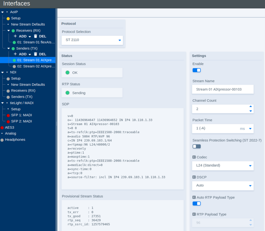
The Status section shows the current operating state of the sender and provides the SDP describing the transmitted stream.
| Parameter | Values | Default | Description |
|---|---|---|---|
| Session Status | Status | - | Shows the overall status of the transmit session. |
| RTP Status | Status | - | Shows whether RTP packets are currently being transmitted. |
| SDP | Status / SDP data | - | Shows the Session Description Protocol data generated for the transmitted stream. This information can be used to configure compatible receivers. |
| Provisional Stream Status | Diagnostic information | - | Provides detailed sender statistics and diagnostic information about the outgoing RTP stream. |
| Reset Sender Status | Button | - | Resets the displayed sender status and diagnostic counters. |
| RTP Status – Leg 1 | Status | - | Shows the transmit status of the first stream leg. |
| RTP Status – Leg 2 | Status | - | Shows the transmit status of the redundant second stream leg when ST 2022-7 is used. |
To copy the complete SDP, move the pointer over the displayed SDP. A copy control appears; click it to copy the SDP to the clipboard. The copied SDP can then be pasted directly into a compatible receiver or another application.
The Provisional Stream Status is primarily intended for diagnostics and troubleshooting. For normal operation, the Session and RTP status indicators provide the most relevant overview.
Settings
The Settings section defines the format and network properties of the transmitted stream.
| Parameter | Values | Default | Description |
|---|---|---|---|
| Enable | On / Off | - | Enables or disables the sender. |
| Stream Name | Text | - | Defines the name used to identify and advertise the transmitted stream. |
| Channel Count | Supported channel counts | - | Defines the number of audio channels carried by the stream. |
| Packet Time | Supported packet times | - | Defines the duration of audio carried by each RTP packet. Shorter packet times reduce transport latency but increase the packet rate and processing load. |
| Seamless Protection Switching (ST 2022-7) | On / Off | - | Enables SMPTE ST 2022-7 seamless protection switching. When enabled, two equivalent stream legs are transmitted over separate network paths. |
| Codec | Available codecs | - | Defines the audio codec or sample format used for the transmitted stream. |
| DSCP | Auto / Available DSCP values | - | Defines the Differentiated Services Code Point used to classify the outgoing RTP traffic for Quality of Service (QoS). Auto applies the DSCP value configured for the corresponding stream type and packet time on the AoIP Setup page. |
| Auto RTP Payload Type | On / Off | - | Automatically assigns the RTP payload type. Disable this option to specify the payload type manually. |
| RTP Payload Type | RTP payload type | - | Defines the RTP payload type when automatic assignment is disabled. |
| RTP Port | Port number | - | Defines the UDP destination port used for the RTP stream. |
| TTL | Number of network hops | - | Defines the IP multicast Time To Live (TTL), limiting how many routed network hops the multicast stream can traverse. |
DSCP (Differentiated Services Code Point) allows network infrastructure to classify AoIP traffic for Quality of Service. Switches and routers can use this marking to give time-critical audio traffic the required priority over less critical network traffic.
Stream Legs
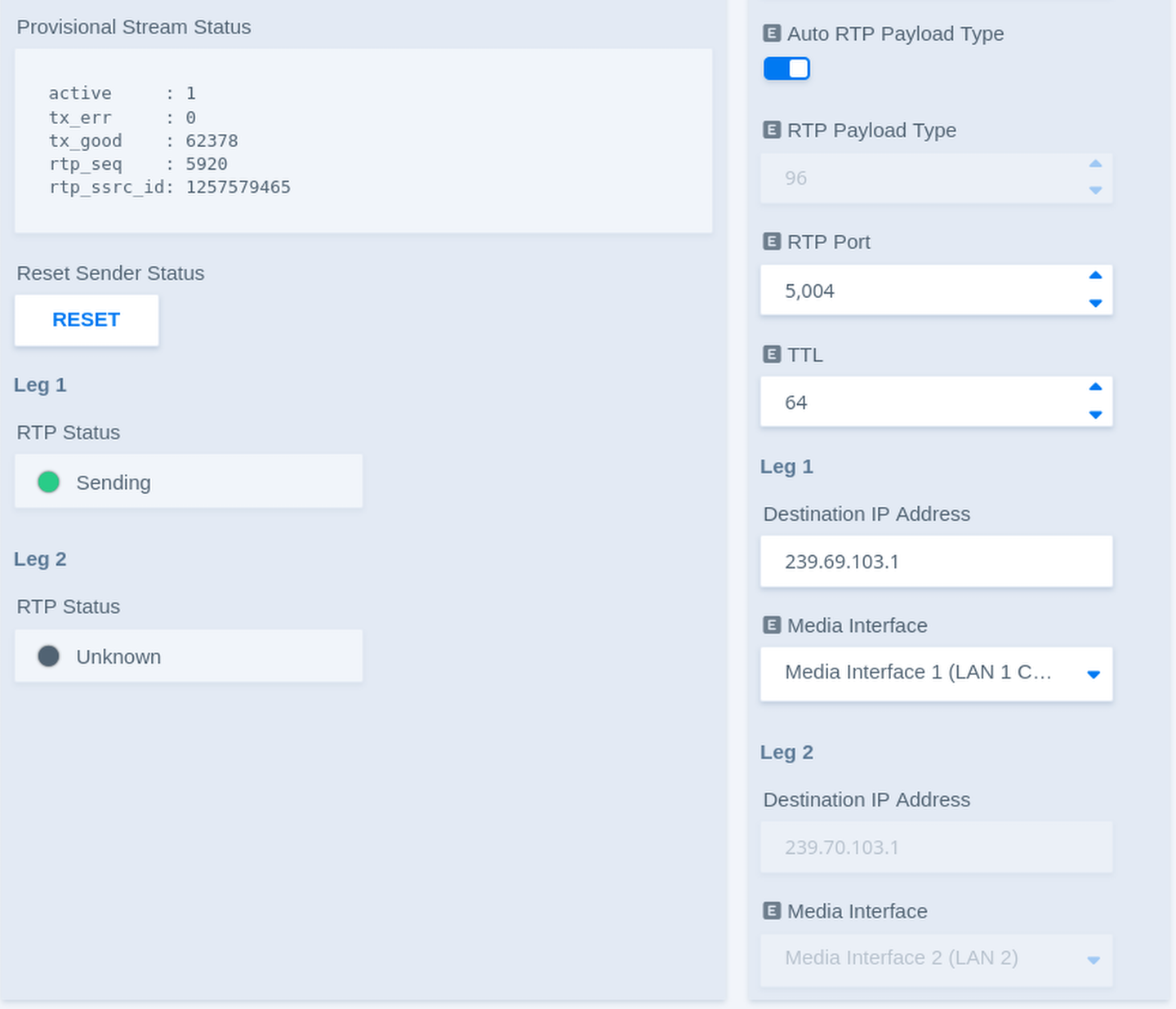
Each sender can use up to two stream legs. Leg 1 carries the primary stream. Leg 2 carries an equivalent redundant stream when ST 2022-7 is enabled.
| Parameter | Values | Default | Description |
|---|---|---|---|
| Destination IP Address – Leg 1 | Multicast IP address | - | Defines the multicast destination address used to transmit the first stream leg. |
| Media Interface – Leg 1 | Available Media Interfaces | - | Selects the Media Interface used to transmit the first stream leg. |
| Destination IP Address – Leg 2 | Multicast IP address | - | Defines the multicast destination address used to transmit the redundant second stream leg. |
| Media Interface – Leg 2 | Available Media Interfaces | - | Selects the Media Interface used to transmit the redundant second stream leg when ST 2022-7 is enabled. |
Each sender can be assigned individually to one of the available Media Interfaces. This allows different senders, and, with ST 2022-7, individual stream legs, to use separate physical AoIP networks.
In combination with the internal audio routing, flexAI can also transfer audio between otherwise independent AoIP networks: audio received through one Media Interface can be routed internally and transmitted again through a sender assigned to another Media Interface. This operates at the audio level rather than as a network bridge.
With ST 2022-7 enabled, both legs carry equivalent audio data over independent network paths. A compatible receiver can use both legs for seamless protection against packet loss or a failure of one network path.
Livewire Sender Settings
When Livewire is selected under Protocol Selection, some sender parameters differ from those used for ST 2110.
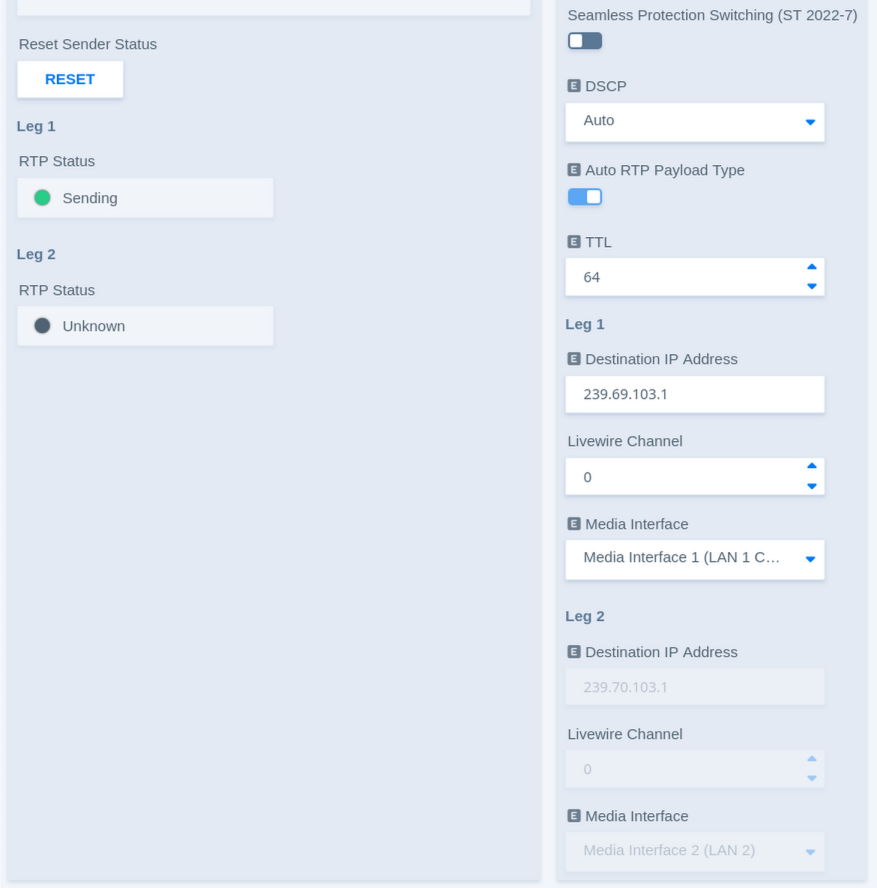
The general sender controls, status information, packet time, DSCP, and redundancy settings operate in the same way as described above. Livewire additionally uses a Livewire Channel to identify the transmitted stream.
| Parameter | Values | Default | Description |
|---|---|---|---|
| Destination IP Address – Leg 1 | Multicast IP address | - | Shows or defines the multicast destination address used for the first Livewire stream leg. |
| Livewire Channel – Leg 1 | Livewire channel number | - | Defines the Livewire Channel used for the first stream leg. The channel number identifies the stream within the Livewire network and corresponds to its multicast destination. |
| Media Interface – Leg 1 | Available Media Interfaces | - | Selects the Media Interface used to transmit the first Livewire stream leg. |
| Destination IP Address – Leg 2 | Multicast IP address | - | Shows or defines the multicast destination address used for the redundant second Livewire stream leg. |
| Livewire Channel – Leg 2 | Livewire channel number | - | Defines the Livewire Channel used for the redundant second stream leg. |
| Media Interface – Leg 2 | Available Media Interfaces | - | Selects the Media Interface used to transmit the redundant second stream leg when ST 2022-7 is enabled. |
As with other sender types, Leg 2 is used when Seamless Protection Switching (ST 2022-7) is enabled.
tieLight / MADI
MADI / tieLight
The tieLight / MADI section configures the SFP-based multichannel audio interfaces available on compatible flexAI systems.
The two SFP interfaces can be operated independently, as a redundant pair, or individually assigned to MADI and tieLight.
MADI and tieLight require different SFP module types and are not interchangeable. When changing an interface between MADI and tieLight, make sure that the appropriate SFP module is installed.
tieLight is a proprietary Jünger Audio point-to-point interface for transporting multichannel audio between compatible systems. It remains supported on compatible hardware but requires additional configuration.
Setup
Select Setup under tieLight / MADI to configure the operating mode of the two interfaces.
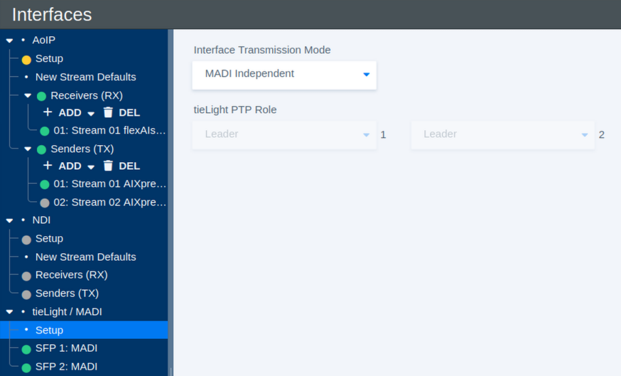
| Parameter | Values | Default | Description |
|---|---|---|---|
| Interface Transmission Mode | MADI Independent / MADI Redundant / tieLight Independent / tieLight Redundant / IF1:MADI IF2:tieLight / IF1:tieLight IF2:MADI | - | Defines how the two SFP interfaces are used and whether they operate independently or as a redundant pair. |
| tieLight PTP Role – Interface 1 | Available PTP roles | - | Defines the PTP role of Interface 1 when it is configured for tieLight. |
| tieLight PTP Role – Interface 2 | Available PTP roles | - | Defines the PTP role of Interface 2 when it is configured for tieLight. |
Interface Transmission Modes
MADI Independent operates both interfaces as separate MADI interfaces. Each interface can carry its own audio signals.
MADI Redundant operates the two interfaces as a redundant MADI pair. Both interfaces carry the same channels, providing an alternative path if one connection fails.
tieLight Independent operates both interfaces as separate tieLight connections.
tieLight Redundant operates the two interfaces as a redundant tieLight pair.
The mixed modes IF1:MADI IF2:tieLight and IF1:tieLight IF2:MADI allow one SFP interface to carry MADI while the other carries tieLight.
When selecting a different transmission mode, also check that the SFP module installed in each interface matches the selected protocol.
The redundancy function monitors the availability of the complete MADI or tieLight signal path. It can switch to the redundant interface if the primary signal is lost, but it does not detect or compensate for failures affecting individual audio channels within an otherwise valid signal.
MADI Interface Status
Select an individual MADI interface, such as SFP 1: MADI or SFP 2: MADI, to view its current receive and signal status.
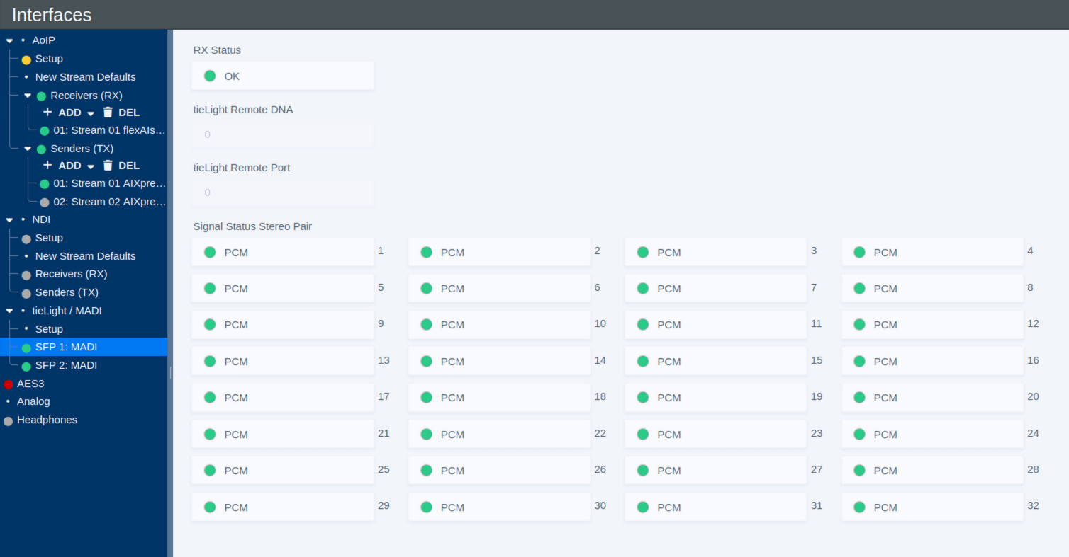
| Parameter | Values | Default | Description |
|---|---|---|---|
| RX Status | Status | - | Shows the overall receive status of the MADI interface. |
| Signal Status Stereo Pair | Status per stereo pair | - | Shows the detected signal status for each of the 32 stereo pairs carried by the 64-channel MADI interface. A status such as PCM indicates that PCM audio is detected for the corresponding pair. |
The per-pair status display provides a quick overview of the incoming MADI signal and can be useful when checking the connection and available audio channels.
tieLight Status
When an SFP interface is operated in tieLight mode, the interface page provides status information for the tieLight connection, including information about the connected remote endpoint.
| Parameter | Values | Default | Description |
|---|---|---|---|
| RX Status | Status | - | Shows the overall receive status of the tieLight interface. |
| tieLight Remote DNA | Status | - | Shows the DNA identifier reported by the remote tieLight device. |
| tieLight Remote Port | Status | - | Shows the remote tieLight port associated with the connection. |
AES3
The AES3 page provides configuration and status information for the system's AES3 inputs and outputs. AES3, also commonly referred to as AES/EBU, is a professional digital audio interface standard for transmitting two channels of audio together with related channel status information.
The interface is organized in stereo pairs. Depending on the selected I/O mode, the available AES3 connections are configured either as 8 Inputs / 8 Outputs or 4 Inputs / 12 Outputs.
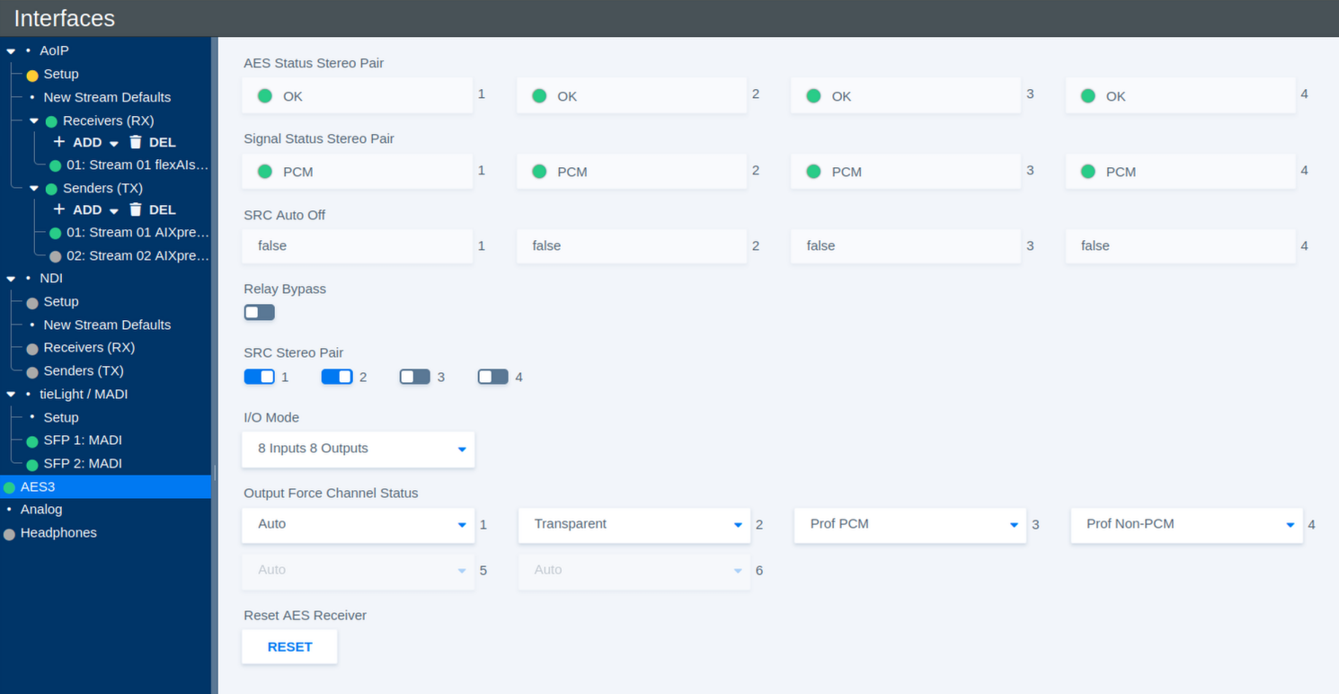
Input Status
The input status indicators provide information about the AES3 signal detected on each stereo pair.
| Parameter | Values | Default | Description |
|---|---|---|---|
| AES Status Stereo Pair | Status | - | Shows whether a valid AES3 signal is detected for each input stereo pair. |
| Signal Status Stereo Pair | Status | - | Shows the detected signal type for each stereo pair, for example **PCM**. |
| SRC Auto Off | Status | - | Shows whether the Sample Rate Converter (SRC) has been automatically disabled for the corresponding stereo pair. |
Sample Rate Conversion
Sample Rate Conversion can be enabled individually for each AES3 input stereo pair.
| Parameter | Values | Default | Description |
|---|---|---|---|
| SRC Stereo Pair 1–4 | On / Off | - | Enables or disables Sample Rate Conversion for the corresponding AES3 input stereo pair. SRC allows incoming AES3 signals with a different or asynchronous sample rate to be converted to the system sample rate. |
Relay Bypass
| Parameter | Values | Default | Description |
|---|---|---|---|
| Relay Bypass | On / Off | - | Activates the AES3 relay bypass path, allowing the corresponding AES3 signal path to bypass normal processing where supported by the hardware. |
I/O Mode
The available AES3 connections can be distributed between inputs and outputs in two ways.
| Parameter | Values | Default | Description |
|---|---|---|---|
| I/O Mode | 8 Inputs 8 Outputs / 4 Inputs 12 Outputs | - | Selects how the available AES3 interfaces are allocated between inputs and outputs. |
Output Channel Status
AES3 carries additional Channel Status information alongside the audio data. The Output Force Channel Status settings define how this information is generated for each AES3 output stereo pair.
| Parameter | Values | Default | Description |
|---|---|---|---|
| Output Force Channel Status | Auto / Transparent / Prof PCM / Prof Non-PCM / Consumer PCM / Consumer Non-PCM | - | Defines the AES3 Channel Status information transmitted with the corresponding output stereo pair. |
The available modes are:
| Mode | Description |
|---|---|
| Auto | Automatically generates channel status information appropriate for the transmitted signal. |
| Transparent | Passes the available incoming channel status information through to the output without intentionally changing its format. |
| Prof PCM | Forces professional AES3 channel status and identifies the signal as linear PCM audio. |
| Prof Non-PCM | Forces professional AES3 channel status and identifies the signal as non-PCM data. |
| Consumer PCM | Forces consumer-format channel status and identifies the signal as linear PCM audio. |
| Consumer Non-PCM | Forces consumer-format channel status and identifies the signal as non-PCM data. |
The Non-PCM modes are intended for signals carrying encoded or other non-linear audio data rather than conventional PCM samples.
Reset AES Receiver
In case an AES3 receiver does not lock correctly to an incoming signal, the corresponding receiver status may remain red.
| Parameter | Values | Default | Description |
|---|---|---|---|
| Reset AES Receiver | Button | - | Resets the AES3 receiver state. If an input does not lock correctly and its status remains red, click Reset to re-establish synchronization with the incoming signal. |
Depending on the hardware platform, the Reset AES Receiver button may not be available. On these systems, receiver recovery is monitored and handled automatically.
Analog
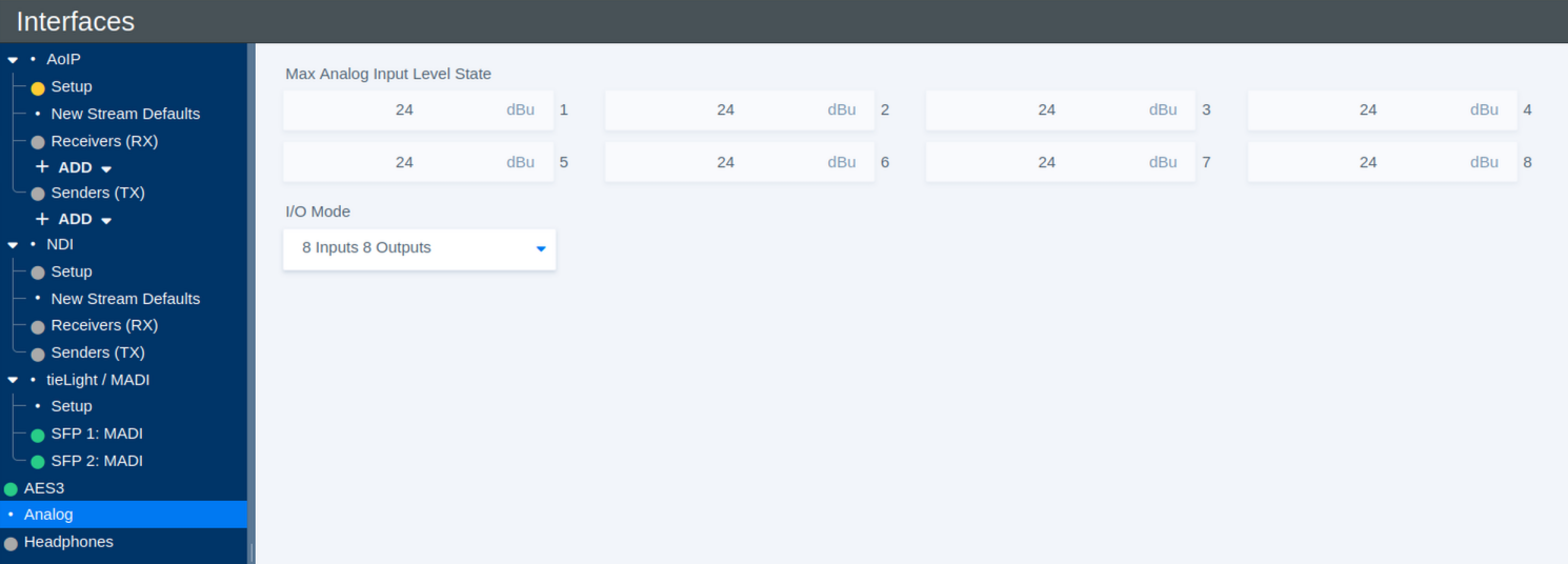
The Analog page provides status information and I/O configuration for the system's analog audio interfaces.
The available number of analog inputs and outputs depends on the selected I/O mode.
Maximum Analog Input Level
The Max Analog Input Level State shows the analog input level that corresponds to 0 dBFS for each input channel.
| Parameter | Values | Default | Description |
|---|---|---|---|
| Max Analog Input Level State | Hardware-dependent, typically +24 dBu or +18 dBu | - | Shows the maximum analog input level corresponding to 0 dBFS for each channel. The value is read from the installed hardware and cannot be changed from the user interface. |
On some hardware variants, the maximum input level can be changed physically by repositioning a jumper on the interface hardware. Depending on the jumper setting, the maximum input level is typically +24 dBu or +18 dBu. The value shown on this page reflects the current hardware configuration.
I/O Mode
| Parameter | Values | Default | Description |
|---|---|---|---|
| I/O Mode | 8 Inputs 8 Outputs / 4 Inputs 12 Outputs | - | Selects how the available analog audio channels are distributed between inputs and outputs. |
Headphone
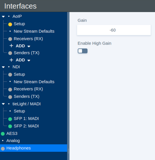
The Headphones page provides level control for the system's headphone output.
Headphone Level
| Parameter | Values | Default | Description |
|---|---|---|---|
| Gain | -80 dBFS to -18 dBFS; up to 0 dBFS with High Gain enabled | - | Sets the headphone output level. With High Gain disabled, the available range is -80 dBFS to -18 dBFS. |
| Enable High Gain | On / Off | - | Extends the available gain range up to 0 dBFS. |