flexAI Software
flexAI software manual
- Overview
- Audio Processing - Processors
- Automixer - Stereo
- Automixer - 5.1
- Delay
- Dolby® E Decoder and Encoder
- Dolby® E Decoder with S-ADM output
- Dolby® ED2 Decoder with S-ADM output
- Dolby® ED2 Encoder
- Downmix Matrix
- Fail Over
- FM Conditioner
- Monitoring Controller - Immersive
- Mix Matrix
- MPEG-H 3D Audio Authoring
- MPEG-H 3D Audio Renderer
- Program Processing Channel Strip – Immersive
- Program Processing Channel Strip – Stereo
- Program Processing Channel Strip – Surround
- S-ADM Authoring
- S-ADM Renderer
- Voice Over Mixer - STEREO
- Voice Over Mixer - SURROUND
- Voice Processing Channel Strip
- Audio Processing - Modules
- Bass Management
- Compressor
- De-Esser
- Delay
- Dolby® E Decoder
- Dolby® ED2 Encoder
- Downmix (5.1)
- Downmix Matrix (12 ch)
- Dynamics
- Equalizer
- Expander
- Fail Over
- FM Conditioner
- Input Conditioner
- Input Leveler
- Level Magic
- Limiter / Failsafe Limiter
- Loudness Measurement
- Monitoring Controller
- MPEG-H Authoring
- Output Conditioner
- Peak Meter
- Phase Rotator
- Speaker ID
- Spectral Signature
- Switch
- Upmix
- Mixer
- MPEG-H 3D Audio Renderer
- Routing
- Interfaces
- Audio over IP - Setup
- Audio over IP - New Stream Defaults
- Audio over IP - Receivers
- Audio over IP - Senders
- tieLight / MADI
- AES3
- Analog
- Headphone
- NDI
- Dante
- Sync
- Workflow
- System
Overview
flexAI - Prerequisit
Note - All products of the flexAI product family such as AIXpressor, flexAIserver, and flexAIcloud employ flexAI as their underlying software platform.
Wherever possible, we have made an effort to point out which information applies to which products, but bear in mind there may be differences between the figures and illustrations in this documentation and your particular product.
Before you start
Before you continue, make sure that:
- The flexAI system has been installed or deployed: flexAI Hardware.
- The system is powered on and running.
- Your computer has network access to the flexAI system.
- You know the IP address or host name of the system.
- A supported web browser is available on your computer.
Getting started
One the system is running, please follow the Setup guide.
Basic Setup
This article describes the first steps after installing or deploying flexAI. It explains how to open the Web UI, log in for the first time, change the admin password, check the basic system configuration, and create a license request.
Use this article as the starting point before configuring audio interfaces, routing, Processors, Modules, or production workflows.
Prerequisites
Before you continue, make sure that:
- The flexAI system has been installed or deployed.
- The system is powered on and running.
- Your computer has network access to the flexAI system.
- You know the IP address or host name of the system.
- A supported web browser is available on your computer.
Detailed prerequisite information can be found in Prerequisites.
Open the Web UI
Open a web browser and enter the IP address or host name of the flexAI system.
Example:
http://<IP address>
or, depending on your system configuration:
https://<IP address>
If the Web UI does not open, check the network connection between your computer and the flexAI system. Also verify the IP address, subnet, gateway, and firewall settings.
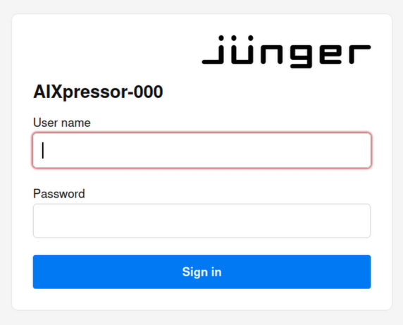
Log In
When the login page appears, enter the initial login credentials.
| Field | Value |
|---|---|
| User name | admin |
| Password | admin |
Select Sign in to open the Web UI.
Change the Admin Password
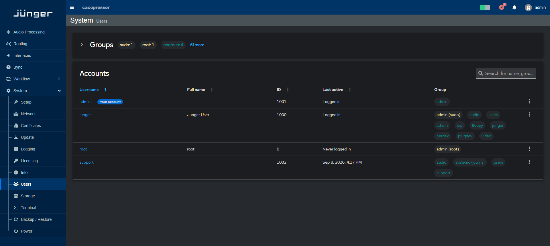
After the first login, the system may show a warning that the default admin password must be changed. Change the password before continuing with the basic setup.
To change the admin password:
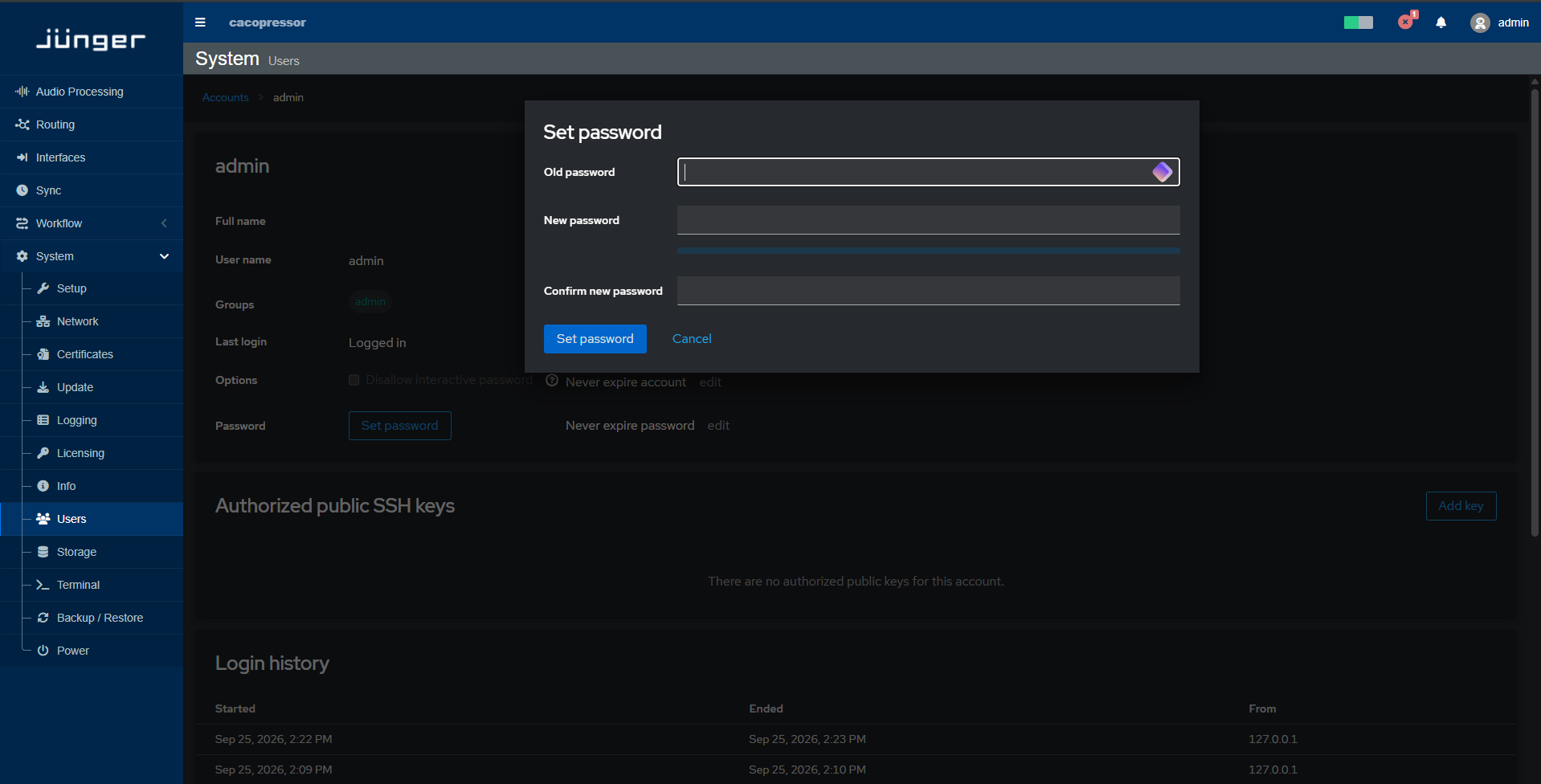
Note - Password must contain at least 10 characters, including at least: - one upper case letter - one lower case letter - one number - one special character
Detailed user management information can be found in Users.
Basic Setup Checklist
After logging in and changing the admin password, check the basic system configuration before using the system in production.
Recommended first setup steps:
- Verify or configure the network settings.
- Check the system name or host name.
- Check date, time, and time synchronization settings.
- Check the installed software version.
- Create a license request from the Licensing page.
- Create a system backup after the initial setup.
These steps help ensure that the system is reachable, identifiable, correctly timed, ready for licensing, and recoverable after initial configuration.
Configure Network Settings
Open the network configuration page and verify the current network settings.
Check the following items:
- Management network interface
- IP address
- Subnet mask or prefix
- Gateway
- DNS settings
- Host name or system name
- Media or AoIP network interfaces, if used
- NTP settings, if time synchronization is required over the network
- PTP settings, if the system is used in an AoIP, AES67, ST 2110, or other PTP-based environment
Make sure the management interface is reachable from the computer used for administration.
Detailed network configuration instructions can be found in Network.
Check System Name and Time Settings
Open the system setup page and verify the basic system information.
Check the following items:
- Host name
- System location, if used in the installation
- System contact, if used in the installation
- Current date
- Current time
The host name helps identify the system in the network and in support or monitoring workflows. Correct date and time settings are important for logs, diagnostics, support cases, and system operation.
Detailed setup information can be found in Setup.
Check Software Version and System Status
Open the Info page and check the current system status and installed software version.
Check the following items:
- Overall system status
- Hardware status
- Software status
- Installed software versions
- System load, if relevant for the installation
The software version is useful when comparing the system state with the manual or when contacting support.
Detailed status and version information can be found in Info.
Create a License Request
Open the Licensing page to create a license request.
Important - Make sure that a dongle is installed in the system or a license server is correctly configured before creating a license request.
To create a license context file to request licenses:
- Open System > Licensing.
- Select Download License Context File.
- Save the license context file to your computer.
- Send the file to the responsible activation or support contact.
- After receiving the license update file, return to the Licensing page.
- Select Upload License Update File to install or update the licenses.
Detailed licensing instructions can be found in Licensing.
Create a Backup
After completing the initial setup, create a system backup.
A backup after the first configuration helps you restore the system to a known working state if settings need to be recovered later.
Before creating the backup, make sure that:
- Network configuration has been completed.
- The admin password has been changed.
- The host name has been checked.
- Date and time settings have been checked.
- The license request has been created or the license update file has been installed.
Detailed backup and restore instructions can be found in Backup / Restore.
Next Steps
After completing the basic setup, continue with the configuration required for your installation.
Recommended next steps:
- Configure audio and media interfaces: Interfaces
- Configure Audio over IP settings, if used: Audio over IP - Setup
- Configure synchronization and clock settings: Sync
- Configure routing connections and Routing Collections: Routing
- Create or verify Processors: Audio Processing - Processors
- Create another backup after the system is fully configured: Backup / Restore
Audio Processing - Processors
Automixer - Stereo
Overview
The Automixer - Stereo is a Processor for combining two stereo program sources with additional mono voice signals. It provides input conditioning, fail-over handling, equalization, level control, voice-over processing, mix-minus generation, clean mono generation, output conditioning, limiting, and metering in one processing chain.
The Processor is intended for stereo production workflows where program audio and voice signals need to be mixed, controlled, and delivered as program, mix-minus, and clean mono outputs.
Typical Applications
Typical applications include:
-
Stereo broadcast program mixing
-
Voice-over integration into stereo program audio
-
Mix-minus generation for production and contribution workflows
-
Clean mono output generation
-
Loudness-controlled stereo output processing
-
Program fail-over workflows
Included Modules
The Stereo version includes the following processing and measurement stages:
-
Input Meter
-
Input Conditioner
-
Fail Over
-
Equalizer
-
Level Magic
-
Voice Over
-
Mix-minus
-
Matrix Mixer
-
True Peak Limiter
-
Output Conditioner
-
Output Meter
-
Loudness Measurement
The signal flow includes separate input conditioning for stereo program and mono voice signals, followed by fail-over selection, equalization, level control, voice-over mixing, mix-minus generation, clean mono generation, output limiting, output conditioning, and measurement.
Channel Formats
This article describes the Stereo version.
Automixer - 5.1
Overview
The Automixer - 5.1 is a Processor for combining two 5.1 program sources with additional mono voice signals. It provides input conditioning, automatic upmixing, equalization, level control, voice-over processing, mix-minus generation, downmixing, output conditioning, limiting, and metering in one processing chain.
The Processor is intended for surround program production workflows where program audio and voice signals need to be mixed, controlled, and delivered in multiple output formats.
Typical Applications
Typical applications include:
-
5.1 broadcast program mixing
-
Voice-over integration into surround program audio
-
Mix-minus generation for production and contribution workflows
-
Clean mono output generation
-
Program downmix generation
-
Loudness-controlled surround output processing
Included Modules
The 5.1 version includes the following processing and measurement stages:
-
Input Meter
-
Input Conditioner
-
Auto Upmix
-
Equalizer
-
Level Magic
-
Voice Over
-
Mix-minus
-
Downmix
-
Matrix Mixer
-
True Peak Limiter
-
Output Conditioner
-
Output Meter
-
Loudness Measurement
The signal flow includes separate input conditioning for program and mono voice signals, followed by upmixing, equalization, level control, voice-over mixing, mix-minus generation, downmixing, output limiting, output conditioning, and measurement.
Channel Formats
This article describes the Surround (5.1) version.
Delay
Overview
The Delay is a Processor for applying delay to 8 or 16 audio channels. It is used to align audio signals in time or to compensate for timing differences between processing, routing, video, or transmission paths.
The Processor provides a dedicated delay stage for multichannel audio workflows. It can be loaded as an 8 or 16 channel version. All channels can be used individually or for multi-channel applications.
Typical Applications
Typical applications include:
-
Audio-to-video synchronization
-
Timing compensation between signal paths
-
Delay alignment in multichannel workflows
-
System integration and routing compensation
-
Satellite link compensation
Included Modules
The 8- and 16-channel versions includes the following processing stage:
-
Delay
The signal flow is:
Input → Delay → Output
Channel Formats
This article describes the 8- and 16-channel versi
Dolby® E Decoder and Encoder
Dolby® E Decoder and Encoder
AIXpressor can optionally be equipped with a Dolby® E decoder and encoder. Please see Adding a Processor for instructions on installing a new processor.
Dolby E Overview
Dolby E was introduced in 1999 as a professional audio coding system that allows the distribution of multichannel digital audio within two-channel infrastructures. Up to eight channels of broadcast-quality audio, plus metadata, can be distributed via a single AES3 pair.
Dolby E Decoder
The decoder will decode all standard Dolby E programs.
Important - Unlike legacy Dolby E implementations in which the second program of a 4x2 configuration appeared on outputs 7/8, AIXpressor always shows the audio outputs in ascending order regardless of which program configuration is being decoded.
Input Page
Click on the Dolby E Decoder button (A), then on the In button (B) to display a running total of the number of frames received (C).
(1)(1)(1)(1).png)
Figure 1 - Dolby E decoder input page
Decoder Page
Click on the Dec button (A) to display a list of all parameters (B), including (but not limited to) the following:
-
Library Version - The version of the installed Dolby library.
-
Input Signal - Green indicates a Dolby E signal; yellow indicates PCM audio; red indicates mute.
-
CRC Errors - Displays the number of CRC errors in the incoming Dolby E stream. The counter can be reset with the Execute button at the bottom of the metadata display.
-
Frame Rate - Indicates the frame rate of the incoming Dolby E signal.
-
Frame Offset - Shows the offset between the incoming Dolby E signal and the system frame reference.
-
Bit Depth - Indicates the bit depth of the incoming Dolby E signal.
-
Program Configuration - Displays the Program Configuration metadata parameter, which determines how the audio channels are grouped within the Dolby E bitstream.
-
Program Description - Shows the Program Description metadata, typically the name of the program or a description of the program source.
-
Channel Mode - The Channel Mode (also known as the Audio coding mode) indicates the active channels within the encoded bitstream. In the decoder, this ensures the proper routing of the audio channels to downstream devices.
-
LFE Channel - Indicates whether or not there is an LFE Channel present in the incoming bitstream.
-
Bitstream Mode - Displays the audio service contained within the incoming Dolby E bitstream.
-
Dialog Normalization - Also referred to as Dialog Level or dialnorm, this indicates the average level of dialog in the presentation and determines the proper level shift in the decoder to ensure proper normalization within and between program sources.
Note - The Decode page displays considerable additional information A detailed explanation of all metadata parameters is available in the Dolby Metadata Guide.
(1)(1)(1)(1)(1)(1).png)
Figure 2 - Dolby E decoder parameter page
Meter Page
Click on the Mtr button (A) to view the decoder meter page. The Peak Level meters (D) show sample-accurate peaks for all eight incoming audio channels with a hold function. Peak Accuracy (B) is currently fixed at sample-accurate resolution. The Peak Hold control (C) allows for Automatic or Manual control of the hold feature. Clicking the Reset Measurement Execute button (E) resets the peak hold indicators.
(1)(1)(1)(1)(1).png)
Figure 3 - Dolbe E decoder meter page
Output Page
Click on the Out button (A) to show the number of clients (B) currently connected to the unit and a running total of the number of frames emitted (C) from the decoder.
.png)
Figure 4 - Dolby decoder output page
Important - Any preset saved and stored in the Dolby E decoder will also be available in the Dolby E encoder, providing an easy way to use the same settings and metadata values. Note that you may receive an error message if the metadata in one of the received programs does not match the program type - for instance, if LFE is activated for a 2/0 Channel Mode of a 5.1+2 Program Configuration. The encoder will automatically correct this, and you may dismiss the message.
Dolby E Encoder
Input Page
Click on the Dolby E Encoder button (A), then on the In button (B) to display a running total of the number of frames received (C).
(1)(1)(1).png)
Figure 5 - Dolby encoder input page
Meter Page
Click on the Mtr button (A) to view the encoder meter page. The Peak Level meters (D) show sample-accurate peaks for all eight encoded audio channels with a hold function. Peak Accuracy (B) is currently fixed at sample-accurate resolution. The Peak Hold control (C) allows for Automatic or Manual control of the hold feature. Clicking the Reset Measurement Execute button (E) resets the peak hold indicators.
(1)(1)(1)(1)(1)(1)(1)(1).png)
Figure 6 - Dolby encdoer meter page
Encoder Page
Click on the Enc button (A) to display a list of all parameters (B), including (but not limited to) the following:
-
Library Version - The version of the installed Dolby library.
-
Encoder Status - Green indicates the encoder is active; red indicates it has stopped.
-
Video Sync Frame Rate Status - Green indicates proper sync; red indicates a mismatch.
-
Video Sync Frame Rate - The actual measured reference frame rate extracted from the sync signal.
-
DSP 1/2 - DSP 7/8 - A label of the encoder inputs based on the signal type to ensure proper encoding for the chosen Program Configuration.
-
Frame Rate - The Frame Rate of the Dolby E-encoded bitstream.
-
Video Sync Shift Offset - Sets the guard band relative to the video switching point (see SMPTE RP 168) to ensure proper Dolby E alignment. Shift steps are measured in audio samples using a 48kHz sample rate.
-
Program Configuration - Sets the Program Configuration metadata parameter, which determines how the audio channels are grouped within the Dolby E bitstream.
-
Program Description - Sets the Program Description metadata, typically the name of the program or a description of the program source.
-
Channel Mode - The Channel Mode (also known as the Audio coding mode) sets the active channels within the encoded bitstream.
-
LFE Channel - Informs the downstream decoder as to whether or not an LFE channel is present.
-
Bitstream Mode - Sets the audio service contained within the incoming Dolby E bitstream.
-
Dialog Normalization - Also referred to as Dialog Level or dialnorm, this sets the average level of dialog in the presentation and determines the proper level shift in the downstream decoder to ensure proper normalization within and between program sources.
-
Line Mode Profile - Sets the dynamic range metadata profile for line outputs of the downstream decoder.
-
RF Mode Profile - Sets the dynamic range metadata profile for the RF outputs of the downstream decoder.
-
DC Filter - Determines whether or not a DC-blocking 3Hz highpass filter is applied prior to encoding to remove DC offsets in the program audio.
-
Lowpass Filter - Determines whether or not a lowpass filter is applied to the main input prior to encoding to remove high frequencies that would not be encoded, thereby preventing aliasing upon decoding.
-
LFE Filter - Determines whether or not a 120Hz eighth-order lowpass filter is applied to the LFE channel prior to encoding, thereby removing frequencies that would cause aliasing when decoded.
Note - A detailed explanation of all metadata parameters is available in the Dolby Metadata Guide.
(1)(1).png)
Figure 7 - Dolby encoder parameter page
Output Page
Click on the Out button (A) to show the number of clients (B) currently connected to the unit and a running total of the number of frames emitted (C) from the encoder.
(1).png)
Figure 8 - Dolby encoder output page
Note - Dolby, Dolby Audio, and the double-D symbol are trademarks of Dolby Laboratories Licensing Corporation. The Dolby E encoder and decoder in AIXpressor are manufactured under license from Dolby Laboratories.
Dolby® E Decoder with S-ADM output
Overview
The Dolby® E Decoder + S-ADM is a Processor for decoding Dolby E content to PCM and making the decoded audio available for workflows that include S-ADM metadata handling.
The Processor is intended for workflows where Dolby E input signals need to be decoded and prepared for downstream immersive or metadata-aware processing. A version without the S-ADM metadata output can be loaded.
Typical Applications
Typical applications include:
-
Dolby E decoding
-
Conversion of encoded contribution signals into decoded audio
-
Preparation of decoded audio for S-ADM workflows
-
Broadcast and production ingest workflows
Included Modules
The Processor includes the following processing and measurement stages:
-
Dolby E Decoder
-
Output Meter
The signal flow is:
Input → Dolby E Decoder → Output Meter → Output
Dolby® ED2 Decoder with S-ADM output
Overview
The Dolby® ED2 Decoder is a Processor for decoding Dolby ED2 input signals into audio that can be used by downstream processing, monitoring, or routing stages.
The Processor is intended for broadcast and immersive audio workflows where Dolby ED2 content must be decoded before further processing.
Typical Applications
Typical applications include:
-
Dolby ED2 decoding
-
Immersive audio ingest workflows
-
Broadcast contribution signal decoding
-
Preparation of decoded audio for monitoring or further processing
Included Modules
The Processor includes the following processing and measurement stages:
-
Dolby E Decoder
-
Output Meter
The signal flow is:
Input → Dolby E Decoder → Output Meter → Output
Dolby® ED2 Encoder
Overview
The Dolby® ED2 Encoder is a Processor for encoding multichannel or immersive audio into Dolby ED2 format.
The Processor is intended for broadcast and contribution workflows where processed audio must be encoded as Dolby ED2 for delivery or downstream transmission.
Typical Applications
Typical applications include:
-
Dolby ED2 encoding
-
Immersive audio contribution workflows
-
Broadcast delivery workflows
-
Encoding of multichannel audio for downstream distribution
Included Modules
The Processor includes the following processing and measurement stages:
-
Input Meter
-
Dolby ED2 Encoder
The signal flow is:
Input → Input Meter → Dolby ED2 Encoder → Output
Downmix Matrix
Overview
The Downmix Matrix is a Processor for creating a downmix from a multichannel input signal. It uses a matrix-based processing stage to derive a lower-channel output format from a higher-channel input format.
The Processor is intended for workflows where immersive or surround content must be made available in a reduced channel format.
Typical Applications
Typical applications include:
-
Creating downmixes from multichannel sources
-
Format conversion for monitoring
-
Generating compatibility outputs
-
Routing multichannel content to lower-channel destinations
Included Modules
The Processor includes the following processing stage:
-
Downmix Matrix
The signal flow is:
Input → Downmix Matrix → Output
Channel Formats
The backup shows a 7.1.4 input-related configuration and an 8-channel output-related configuration.
[PLACEHOLDER: confirm exact input and output channel format naming]
Block Diagram
[PLACEHOLDER: insert block diagram for Downmix Matrix]
Notes
[PLACEHOLDER: block diagram required]
[PLACEHOLDER: confirm target downmix format]
Fail Over
Overview
The Fail Over - Stereo (+Conditioner) is a Processor for stereo source fail-over with input and output conditioning. It selects or switches between stereo signal paths and provides conditioning before and after the fail-over stage.
The Processor is intended for workflows that require a conditioned backup or fallback source path for stereo audio.
Typical Applications
Typical applications include:
-
Stereo program fail-over
-
Backup source switching
-
Conditioned fallback signal paths
-
Operational redundancy in broadcast workflows
Included Modules
The Stereo version includes the following processing stages:
-
Input Conditioner
-
Fail Over
-
Output Conditioner
The signal flow is:
Input → Input Conditioner → Fail Over → Output Conditioner → Output
Channel Formats
This article describes the Stereo version.
The backup also shows an 8-channel layout associated with the Processor configuration.
Block Diagram
[PLACEHOLDER: insert block diagram for Fail Over - Stereo (+Conditioner)]
Notes
[PLACEHOLDER: block diagram required]
[PLACEHOLDER: confirm whether the 8-channel layout is user-facing or internal]
FM Conditioner
Overview
The FM Conditioner Channel Strip - Stereo is a Processor for stereo program processing with a special FM conditioning stage for preparing the audio signal for FM broadcast. It combines input measurement, input conditioning, fail-over handling, phase rotation, de-essing, spectral processing, equalization, dynamics processing, loudness control, FM conditioning, output conditioning, and measurement.
The Processor is intended for stereo broadcast workflows that require a complete program processing chain including FM-oriented signal conditioning. The Processor is for pre-conditioning only and does not replace the functionality of a stereo coder.
Please see the FM Conditioner Module description for detailed setup instructions.
Typical Applications
Typical applications include:
-
Stereo FM program processing
-
Spectral program shaping
-
Program fail-over workflows
-
De-essing and phase optimization
-
Loudness-controlled stereo output processing
-
Generation of program and monitor outputs
Included Modules
The Stereo version includes the following processing and measurement stages:
-
Loudness Measurement
-
Input Conditioner
-
Fail Over
-
Phase Rotator
-
De-Esser
-
Spectral Signature
-
Equalizer
-
Expander
-
Compressor
-
Level Magic
-
FM Conditioner
-
Output Conditioner
The signal flow includes input measurement and conditioning for two stereo sources, fail-over selection, phase rotation, de-essing, spectral signature processing, equalization, expansion, compression, loudness control, FM conditioning, output conditioning, and output measurement.
Channel Formats
This article describes the Stereo version.
Monitoring Controller - Immersive
Overview
The Immersive Monitoring Controller is a Processor for immersive production workflows. It combines input metering, input conditioning, source switching, monitoring control, monitor mix processing, downmixing, bass management, equalization, sample playback, output conditioning, and output metering.
The Processor is intended for controlled monitoring of 7.1.4 (lower channel configurations can be loaded) audio in production, quality-control, and immersive audio environments.
Typical Applications
Typical applications include:
-
7.1.4 immersive audio monitoring
-
Source switching between monitoring inputs
-
Monitor mix control
-
Downmix monitoring
-
Bass management
-
Room or monitor equalization
-
Output conditioning and metering
Included Modules
The 7.1.4 version includes the following processing and measurement stages:
-
Input Meter
-
Input Conditioner
-
Buffer Multiplexer
-
MAP Monitoring Controller
-
MAP Mix
-
Downmix Multichannel
-
Bass Management
-
Equalizer
-
Sampler
-
Output Conditioner
-
Output Meter
The signal flow includes input measurement and conditioning for two 7.1.4 sources, source switching, monitoring control, monitor mix processing, downmixing, bass management, equalization, sample playback, output conditioning, and output metering.
Channel Formats
This article describes the 7.1.4 version. Lower channel configurations can be loaded utilizing the same license.
Mix Matrix
Overview
The Mix Matrix - 16 Ch is a Processor for matrix-based mixing and routing of multichannel audio. It provides a flexible mix matrix stage for creating output signals from multiple input channels.
The Processor is intended for workflows that require channel combining, distribution, or custom signal matrixing.
Typical Applications
Typical applications include:
-
Multichannel mix matrixing
-
Custom channel routing
-
Signal distribution
-
Combining or deriving output channels from multiple inputs
Included Modules
The 16-channel version includes the following processing stage:
-
Mix Matrix
The signal flow is:
Input → Mix Matrix → Output
Channel Formats
This article describes the 16-channel version.
The backup also shows an 8-channel layout associated with the Processor configuration.
Block Diagram
[PLACEHOLDER: insert block diagram for Mix Matrix - 16 Ch]
Notes
[PLACEHOLDER: block diagram required]
[PLACEHOLDER: confirm whether the 8-channel layout is user-facing or internal]
MPEG-H 3D Audio Authoring
Overview
The MPEG-H 3D Audio Authoring Processor is used to prepare audio and metadata for MPEG-H 3D Audio workflows. It provides an authoring stage with input and output metering for the audio path.
The Processor is intended for workflows where MPEG-H 3D Audio content is created or prepared before rendering, monitoring, or delivery.
Typical Applications
Typical applications include:
-
MPEG-H 3D Audio authoring
-
Preparation of immersive audio content
-
Metadata-aware production workflows
-
Input and output monitoring of authored audio
Included Modules
The Processor includes the following processing and measurement stages:
-
Input Meter
-
MPEG-H 3D Audio Authoring
-
Output Meter
The signal flow is:
Input → Input Meter → MPEG-H 3D Audio Authoring → Output Meter → Output
MPEG-H 3D Audio Renderer
Overview
The MPEG-H 3D Audio Renderer is a Processor for rendering MPEG-H 3D Audio content for monitoring and output measurement. It combines MPEG-H rendering with a linked monitor controller and loudness measurement.
The Processor is intended for immersive audio workflows where MPEG-H content must be rendered and monitored in a controlled output format.
Typical Applications
Typical applications include:
-
MPEG-H 3D Audio rendering
-
Immersive audio monitoring
-
Renderer output loudness measurement
-
Production and quality-control monitoring workflows
Included Modules
The Processor includes the following processing and measurement stages:
-
Input Meter
-
MPEG-H 3D Audio Renderer
-
Monitor Controller Linked
-
Loudness Measurement
The signal flow includes MPEG-H rendering, linked monitor control, and output loudness measurement.
Program Processing Channel Strip – Immersive
Overview
The Program Processing Channel Strip - 7.1.4 (+Upmix) is a Processor for immersive program processing with automatic upmixing. It combines input measurement, input conditioning, upmixing, equalization, expansion, compression, loudness control, output conditioning, and loudness measurement.
The Processor is intended for 7.1.4 program workflows where source material needs to be processed, upmixed, controlled, and delivered as an immersive output.
Typical Applications
Typical applications include:
-
7.1.4 immersive program processing
-
Upmix-assisted immersive workflows
-
Equalization and dynamics control
-
Loudness-controlled immersive output processing
-
Broadcast and production workflows using 7.1.4 audio
Included Modules
The 7.1.4 version includes the following processing and measurement stages:
-
Loudness Measurement
-
Input Conditioner
-
Auto Upmix
-
Equalizer
-
Expander
-
Compressor
-
Level Magic
-
Output Conditioner
The signal flow includes input measurement and conditioning, automatic upmixing, equalization, expansion, compression, loudness control, output conditioning, and output measurement.
Channel Formats
This article describes the 7.1.4 version with upmixing. Lower configurations (5.1.4) with and without upmixing can be loaded.
Program Processing Channel Strip – Stereo
Overview
The Program + Spectral Processing Channel Strip - Stereo is a Processor for stereo program processing with spectral signature processing. It combines input measurement, input conditioning, fail-over handling, spectral processing, equalization, expansion, compression, loudness control, output conditioning, and loudness measurement.
The Processor is intended for stereo program workflows where tonal shaping, dynamics control, source fail-over, and loudness control are required in one processing chain.
Typical Applications
Typical applications include:
-
Stereo broadcast program processing
-
Spectral program shaping
-
Program fail-over workflows
-
Dynamic range control
-
Loudness-controlled stereo output processing
Included Modules
The Stereo version includes the following processing and measurement stages:
-
Loudness Measurement
-
Input Conditioner
-
Fail Over
-
Spectral Signature
-
Equalizer
-
Expander
-
Compressor
-
Level Magic
-
Output Conditioner
The signal flow includes input measurement and conditioning for two stereo sources, fail-over selection, spectral signature processing, equalization, expansion, compression, loudness control, output conditioning, and output measurement.
Channel Formats
This article describes the Stereo version.
Block Diagram
[PLACEHOLDER: insert block diagram for Program + Spectral Processing Channel Strip - Stereo]
Notes
[PLACEHOLDER: block diagram required]
Program Processing Channel Strip – Surround
Overview
The Program + Spectral Processing Channel Strip - 5.1 is a Processor for 5.1 program processing with spectral signature processing. It combines input measurement, input conditioning, automatic upmixing, spectral processing, equalization, expansion, compression, loudness control, output conditioning, and loudness measurement.
The Processor is intended for surround program workflows where tonal shaping, dynamics control, and loudness control are required in one processing chain.
Typical Applications
Typical applications include:
-
5.1 broadcast program processing
-
Spectral program shaping
-
Upmix-assisted surround workflows
-
Dynamic range control
-
Loudness-controlled 5.1 output processing
Included Modules
The 5.1 version includes the following processing and measurement stages:
-
Loudness Measurement
-
Input Conditioner
-
Input Meter
-
Auto Upmix
-
Spectral Signature
-
Equalizer
-
Expander
-
Compressor
-
Level Magic
-
Output Conditioner
The signal flow includes input measurement and conditioning for two 5.1 sources and one mono source, automatic upmixing, spectral signature processing, equalization, expansion, compression, loudness control, output conditioning, and output measurement.
Channel Formats
This article describes the Surround (5.1) version.
S-ADM Authoring
Overview
The Processor is intended for workflows where S-ADM content is created, prepared, or passed into downstream rendering, monitoring, or delivery processes.
Typical Applications
Typical applications include:
Included Modules
The Processor includes the following processing and measurement stages:
-
Input Meter
-
S-ADM Authoring
-
Output Meter
The signal flow is:
Input → Input Meter → S-ADM Authoring → Output Meter → Output
S-ADM Renderer
Overview
The S-ADM Dolby Renderer is a Processor for rendering S-ADM content for monitoring and output measurement. It combines S-ADM rendering with a linked monitor controller and loudness measurement.
The Processor is intended for immersive audio workflows where S-ADM content must be rendered and monitored in a controlled output format.
Typical Applications
Typical applications include:
-
S-ADM rendering
-
Immersive audio monitoring
-
Renderer output loudness measurement
-
Production and quality-control monitoring workflows
Included Modules
The Processor includes the following processing and measurement stages:
-
Input Meter
-
S-ADM Renderer
-
Monitor Controller Linked
-
Loudness Measurement
The signal flow includes S-ADM rendering, linked monitor control, and output loudness measurement.
Voice Over Mixer - STEREO
Overview
The Voice Over Mixer - Stereo is a Processor for combining a stereo main program signal with up to six mono voice signals. It provides input conditioning, voice-over processing, mix-minus generation, matrix mixing, level control, true peak limiting, output conditioning, and measurement.
The Processor is intended for stereo voice-over workflows where a main stereo program and up to six mono voice sources need to be combined and delivered in multiple output formats.
Typical Applications
Typical applications include:
-
Stereo program voice-over mixing
-
Up to six voice production workflows
-
Mix-minus generation
-
Clean mono output generation
-
Loudness-controlled stereo output processing
Included Modules
The Processor includes the following processing and measurement stages:
-
Input Meter
-
Input Conditioner
-
Voice Over
-
Mix-minus
-
Matrix Mixer
-
Level Magic
-
True Peak Limiter
-
Output Conditioner
-
Output Meter
-
Loudness Measurement
The signal flow includes input conditioning for the main stereo program and up to six mono voice sources, voice-over mixing, mix-minus generation, clean mono generation, level control, limiting, output conditioning, and measurement.
Channel Formats
This article describes a stereo main program version with up to six mono voice inputs.
The Processor uses stereo, mono, and clean mono output-related paths.
Block Diagram
[PLACEHOLDER: insert block diagram for Voice Over Mixer - Main Stereo + 2x Mono]
Notes
[PLACEHOLDER: block diagram required]
Voice Over Mixer - SURROUND
Overview
The Voice Over Mixer - Surround is a Processor for combining a 5.1 main program signal with up to six mono voice signals. It provides input conditioning, voice-over processing, mix-minus generation, downmixing, matrix mixing, level control, true peak limiting, output conditioning, and measurement.
The Processor is intended for surround voice-over workflows where a main 5.1 program and two mono voice sources need to be combined and delivered in multiple output formats.
Typical Applications
Typical applications include:
-
5.1 program voice-over mixing
-
Up to six voice production workflows
-
Mix-minus generation
-
Program downmix generation
-
Clean mono output generation
-
Loudness-controlled surround output processing
Included Modules
The Processor includes the following processing and measurement stages:
-
Input Meter
-
Input Conditioner
-
Voice Over
-
Mix-minus
-
Downmix
-
Matrix Mixer
-
Level Magic
-
True Peak Limiter
-
Output Conditioner
-
Output Meter
-
Loudness Measurement
The signal flow includes input conditioning for the main 5.1 program and two mono voice sources, voice-over mixing, mix-minus generation, downmixing, clean mono generation, level control, limiting, output conditioning, and measurement.
Channel Formats
This article describes a 5.1 main program version with up to six mono voice inputs.
The Processor uses 5.1, mono, stereo, and clean mono output-related paths.
Block Diagram
[PLACEHOLDER: insert block diagram for Voice Over Mixer - Main 5.1 + 2x Mono]
Notes
[PLACEHOLDER: block diagram required]
Voice Processing Channel Strip
Overview
The Voice Processing Channel Strip is a Processor for processing a single voice signal. It combines input conditioning, voice leveling, phase rotation, de-essing, equalization, dynamics processing, loudness control, output conditioning, and metering in one signal chain.
The Processor is intended for professional voice processing where a consistent, controlled, and broadcast-ready voice signal is required.
Typical Applications
Typical applications include:
-
Voice-over and narration processing
-
Broadcast voice processing
-
Podcast and studio voice processing
-
Loudness control for voice recordings
-
Dynamic range control for speech signals
-
Audio book production
Included Modules
The mono and stereo versions includes the following processing and measurement stages:
-
Input Meter
-
Input Conditioner
-
Voice Leveler
-
Phase Rotator
-
De-Esser
-
Equalizer
-
Advanced Dynamics
-
Level Magic
-
Output Conditioner
-
Output Meter
The signal flow is:
Input → Input Meter → Input Conditioner → Voice Leveler → Phase Rotator → De-Esser → Equalizer → Advanced Dynamics → Level Magic → Output Conditioner → Output Meter → Output
Channel Formats
This article describes the mono and stereo version.
The Voice Processing Channel Strip is also available as a stereo version. Dual-mono operation is not supported.
Audio Processing - Modules
Bass Management
Applicability
This description applies to the Surround and Immersive version of the Bass Management module.
Overview
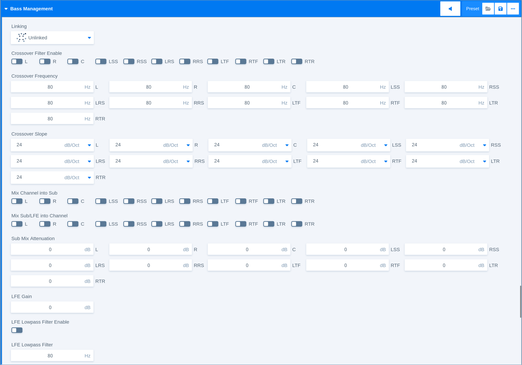
Bass Management is a module for managing low-frequency content in an immersive monitoring setup. It can route low-frequency components from main channels to a subwoofer path and can also control how LFE content is filtered and reproduced.
Processing Principle
The module applies crossover filters to selected channels and controls how signal components are mixed into or out of the subwoofer path. The grouping parameter determines how channel controls are linked or separated.
Parameters
|
Parameter |
Description |
|
Linking |
Controls how channel parameters are linked for common operation. |
|
Crossover Filter Enable |
Enables or disables crossover filtering for a channel. |
|
Crossover Frequency |
Sets the crossover frequency for a channel. |
|
Crossover Slope |
Selects the crossover filter slope for a channel. |
|
Mix Channels into Sub |
Controls whether channel content is mixed into the subwoofer path. |
|
Mix Sub/LFE into Channel |
Controls whether subwoofer content is mixed back into a main channel path. |
|
Sub Mix Attenuation |
Adjusts attenuation for the subwoofer mix contribution. |
|
LFE Gain |
Adjusts the LFE channel level in the bass management path. |
|
LFE Low-pass Filter Enable |
Enables or disables low-pass filtering for the LFE path. |
|
LFE Low-pass Filter |
Sets the LFE low-pass filter behavior. |
Related Processors
-
Monitoring Controller
Compressor
Applicability
This description applies to the Stereo, Surround, and Immersive versions of the Compressor module.
Overview
Compressor is a module for reducing the dynamic range of a signal. It is used to control level variations and increase consistency before later loudness control or output processing stages.
Processing Principle
The module adjusts signal level according to the selected reference level, ratio, range, and processing profile. Grouping controls whether channels are processed together or independently. The upward compression principle follows the characteristics of the legendary "Jünger Compressors" from the late 1980s and 1990s.
Parameters
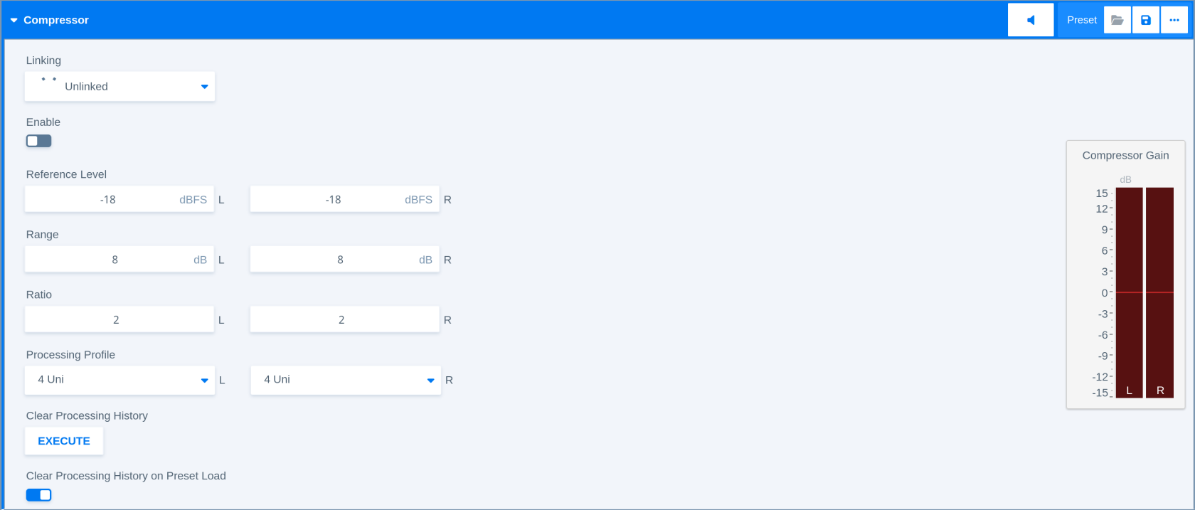
|
Parameter |
Description |
|
Linking |
Controls how channels are linked in the sidechain for compression. |
|
Enable |
Enables or disables the compressor stage. |
|
Reference Level |
Sets the reference level used by the compressor. The reference level is the point where the compression response curve crosses with the linear response. |
|
Range |
Limits the maximum compression range. The range parameter works symmetrical (above and below reference level). |
|
Ratio |
Sets the amount of compression by the steepness of the response curve. |
|
Processing Profile |
Selects the compressor processing profile which represent the attack and release timings of the processor. |
|
Clear Processing History |
Clears the internal processing history when applied or when a preset is loaded. |
Related Processors
-
FM Conditioner Channel Strip - Stereo
-
Program Processing Channel Strip - Stereo
-
Program Processing Channel Strip - Surround
-
Program Processing Channel Strip - Immersive
De-Esser
Applicability
This description applies to the Mono and Stereo versions of the De-Esser module.
Overview
De-Esser is a module for reducing excessive sibilance or harsh high-frequency components in speech and program material.
Processing Principle
The module detects signal energy in a selected frequency range and reduces it according to the configured filter and range settings. Grouping controls whether channels are processed together or independently.
Parameters
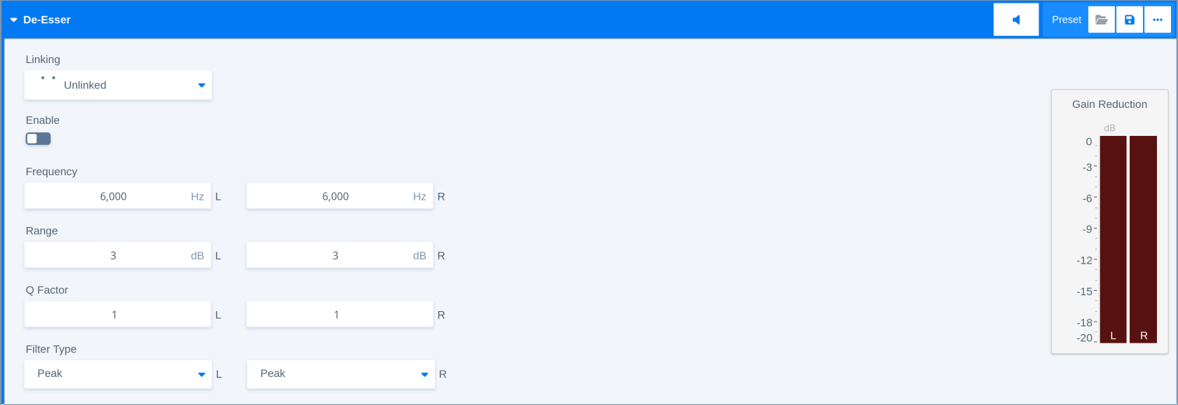
|
Parameter |
Description |
|
Linking |
Controls how channel parameters are linked and the sidechain is grouped for de-essing. |
|
Enable |
Enables or disables the de-esser stage. |
|
Frequency |
Sets the center or cutoff frequency used by the de-esser filter. |
|
Range |
Limits the maximum amount of de-essing. |
|
Q Factor |
Sets the quality (inverse bandwidth) or selectivity of the de-esser filter. |
|
Filter Type |
Selects the filter type used for sibilance detection or reduction. |
Related Processors
-
FM Conditioner Channel Strip - Stereo
-
Voice Processing Channel Strip - Mono
-
Voice Processing Channel Strip - Stereo
Delay
Applicability
This description applies to the 8-channel and 16-channel version of the Delay module.
Overview
Delay is a module for delaying audio signals for longer periods of time. It is used to compensate for timing differences between signal paths, devices, or audio and video paths. It's maximum delay time allows for compensating even longest delays caused by satellite links or similar applications.
Processing Principle
The module delays each signal path according to the configured coarse and fine delay values. Both values add up to the total delay time.
Parameters
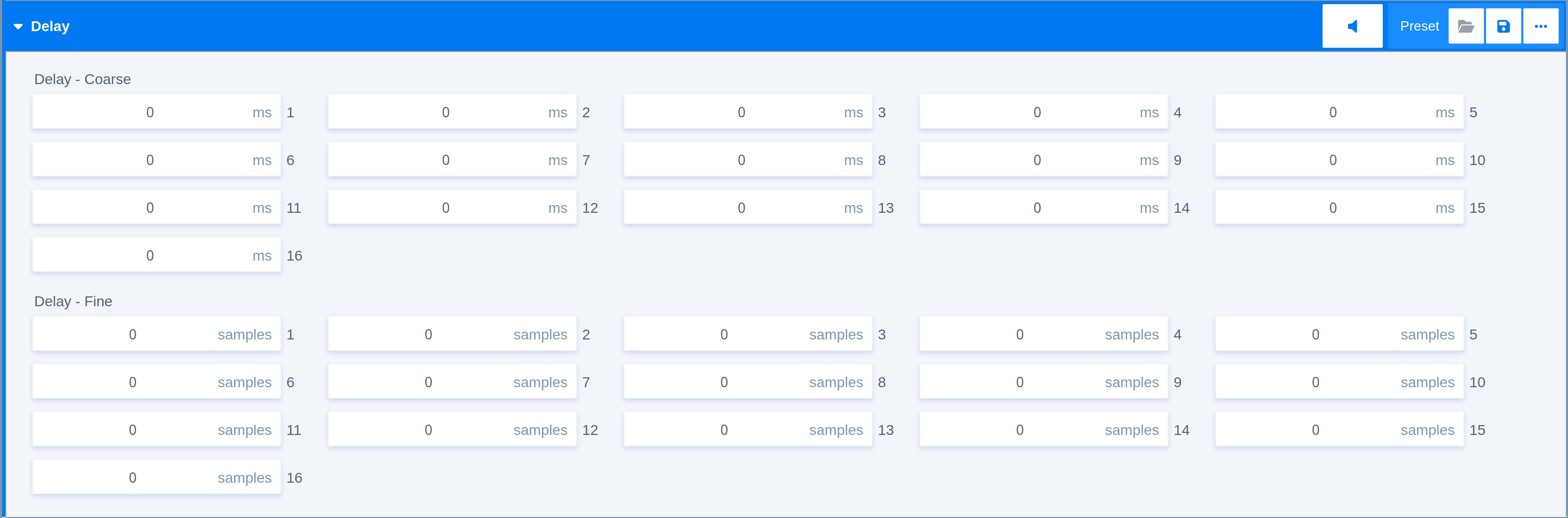
|
Parameter |
Description |
|
Delay Coarse |
Sets the coarse delay amount in milliseconds. |
|
Delay Fine |
Sets the fine delay amount in samples. |
Related Processors
-
Delay - 16 Ch
-
Delay - 8 Ch
Dolby® E Decoder
Applicability
This description applies to the Dolby® E decoding module used by the Dolby E Decoder and Dolby E Decoder + S-ADM Processors.
Overview
Dolby E Decoder is a module for decoding Dolby E encoded input signals into decoded PCM audio for downstream routing, processing, or rendering.
Processing Principle
The module decodes the incoming encoded signal to PCM audio. The version with an S-ADM output exposes program-related metadata information according to the configured program mapping and metadata settings and makes it available in the flexAI routing for further modification or transport.
Parameters
|
Parameter |
Description |
|
Program Channel Mapping |
Controls how decoded program channels are mapped to the output. |
|
Program Language |
Sets or displays the program language metadata. |
|
Program in Metadata |
Selects or identifies the program information contained in the metadata. |
|
Reset CRC Errors |
Resets the CRC error counter or error state when applied or when a preset is loaded. |
Related Processors
-
Dolby® E Decoder
-
Dolby® E Decoder + S-ADM
Dolby® ED2 Encoder
Applicability
This description applies to the Dolby® ED2 Encoder module.
Overview
Dolby ED2 Encoder is a module for encoding audio and associated metadata into Dolby ED2 format.
Processing Principle
The module combines the audio input with the configured metadata to generate a Dolby ED2 encoded output. Dolby ED2 can hold up to 16 audio channels.
Parameters
|
Parameter |
Description |
|
Frame Rate |
Selects the video or transport frame rate used for encoding. |
|
Metadata Mode |
Selects how metadata is supplied to the encoder. |
|
Metadata XML |
Provides or displays XML metadata used by the encoder. |
|
S-ADM XML |
Provides or displays S-ADM XML metadata used by the encoder. |
|
Video Sync Shift Offset |
Sets the video synchronization offset used by the encoder. |
Related Processors
-
Dolby® ED2 Encoder
Downmix (5.1)
Applicability
This description applies to the downmix module used in several processors as an input format converter or as an inter-stage converter.
Overview
Downmix is a module typically used to derive a stereo program downmix from a 5.1 program path.
Processing Principle
The module mixes surround channels into a stereo output using center and surround mix levels. The overall output gain can be modified.
Parameters

|
Parameter |
Description |
|
Center Mix Level |
Sets the contribution level of the center channel in the stereo downmix. When set to 0, the center signal will be mixed into both stereo output channels with no gain change. |
|
Surround Mix Level |
Sets the contribution level of the surround channels in the stereo downmix. LS is only mixed into L, while RS is only mixed into R. Cross mixing of both channels is not supported. When set to 0, the signals will be mixed into the stereo output channels with no gain change. |
|
Output Gain |
Adjusts the overall downmix output level. |
Related Processors
-
Automixer - 5.1
-
Voice Over Mixer - Main 5.1 + 2x Mono
-
Other stereo processors with optional input downmix selected
Downmix Matrix (12 ch)
Applicability
This description applies to the Downmix Matrix module used by the Downmix Matrix Processor.
Overview
Downmix Matrix is a module for matrix-based conversion from a higher-channel input format to a lower-channel output format. It provides input format selection, per-input contribution control, output gain, and limiter-related controls.
Processing Principle
The module maps input channels to output channels using destination assignments and destination gains. Additional (optional) input controls can adjust delay, gain, polarity, and mute state before the matrix contribution is applied.
Parameters
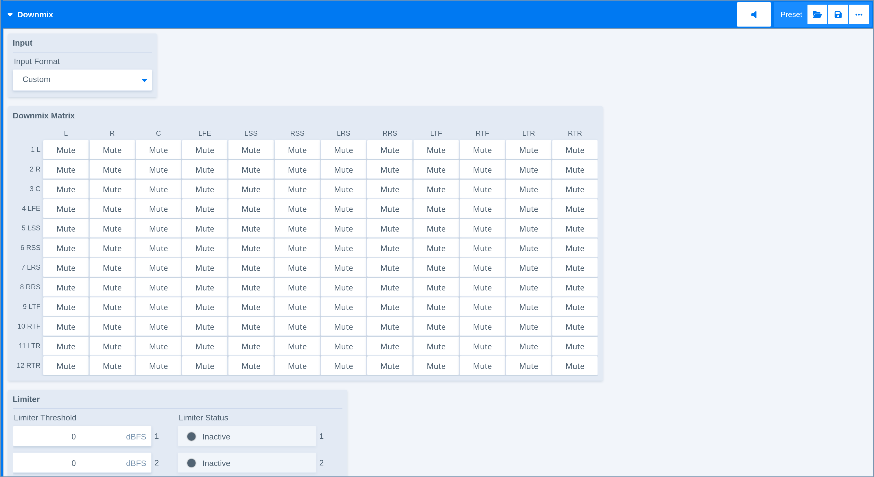
|
Parameter - Input and Matrix Routing |
Description |
|
Input Format |
Selects the input channel format used by the matrix and deactivates unused input channels. |
|
Matrix |
Sets the mix gain or mute for each matrix connection. |
|
Limiter Threshold |
Sets the threshold used by the limiter stage in the matrix output path. |
Related Processors
-
Downmix Matrix
Dynamics
Applicability
This description applies to the Mono and Stereo version of the Dynamics module.
Dynamics is used in the Voice Processing Channel Strip. In block diagrams and Processor layouts, the module may also appear as Advanced Dynamics or Dyn.
Overview
Dynamics is a module for detailed dynamic range control of a voice signal. It combines compressor, expander, upward and downward compression, side-chain filtering, lookahead processing, and soft limiting in one processing stage.
The module is intended for speech and voice processing where dynamic control must be more detailed than a simple compressor or expander stage.
Processing Principle
The module analyzes the signal level and applies gain changes according to the configured compression, expansion, and limiting settings. Downward compression reduces level differences above the selected threshold, while upward compression can raise lower-level signal components toward a reference level.
The expander stage can reduce low-level signal components, and the soft limiter can control peaks at the end of the dynamics stage. Side-chain filters can be used to shape the detector signal that controls the dynamics behavior.
Parameters
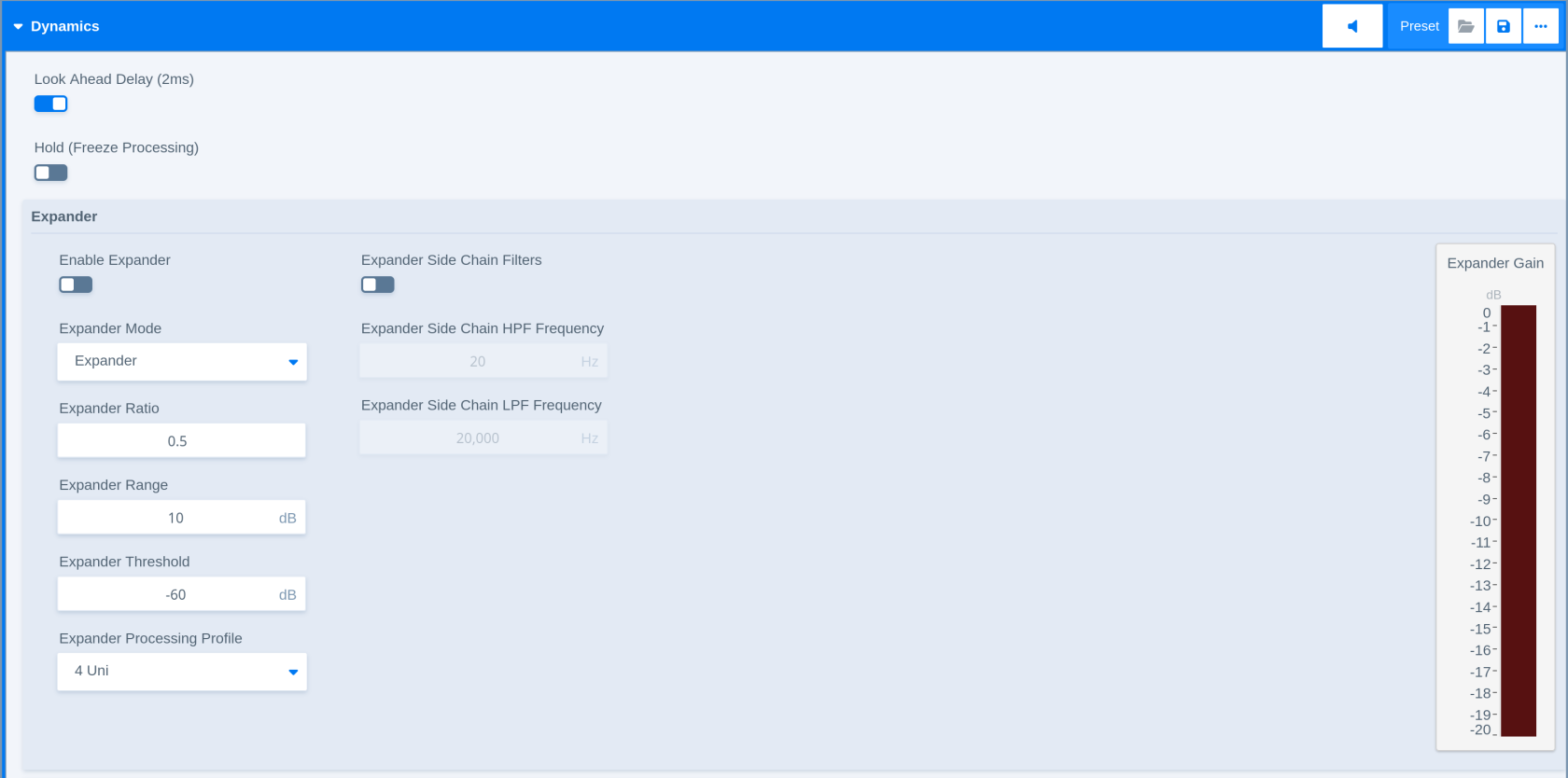
|
Parameter - Expander |
Description |
|---|---|
|
Expander Enable |
Enables or disables the expander stage. |
|
Expander Mode |
Selects the expander operating mode. |
|
Expander Threshold |
Sets the level below which expansion becomes active. |
|
Expander Ratio |
Sets the amount of expansion below the threshold. |
|
Expander Range |
Limits the maximum gain reduction applied by the expander. |
|
Expander Processing Profile |
Selects the processing profile for the expander. |
|
Parameter - Expander Side Chain Filter |
Description |
|
Expander Side-chain Filters Enable |
Enables or disables side-chain filtering for the expander. |
|
Expander Side-chain HPF Frequency |
Sets the high-pass filter frequency used in the expander side chain. |
|
Expander Side-chain LPF Frequency |
Sets the low-pass filter frequency used in the expander side chain. |
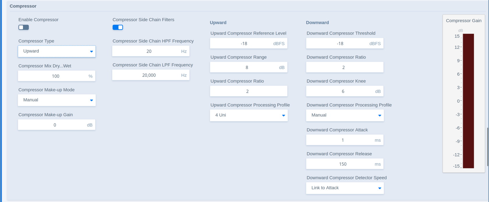
|
Parameter - Compressor |
Description |
|---|---|
|
Compressor Enable |
Enables or disables the compressor stage. |
|
Compressor Type |
Selects the compressor operating type between a traditional downward compressor and the classic ‘Jünger style’ upward compressor. |
|
Compressor Mix Dry/Wet |
Sets the blend between the unprocessed and compressed signal. |
|
Compressor Make-up Mode |
Selects how make-up gain is applied after compression. |
|
Compressor Make-up Gain |
Adjusts the gain applied after compression. |
|
Parameter - Compressor Side Chain Filter |
Description |
|
Compressor Side-chain Filters Enable |
Enables or disables side-chain filtering for the compressor. |
|
Compressor Side-chain HPF Frequency |
Sets the high-pass filter frequency used in the compressor side chain. |
|
Compressor Side-chain LPF Frequency |
Sets the low-pass filter frequency used in the compressor side chain. |
|
Parameter - Upward Compressor |
Description |
|
Upward Compressor Reference Level |
Sets the reference level used by the compressor. The reference level is the point where the compression response curve crosses with the linear response. |
|
Upward Compressor Range |
Limits the maximum compression range. The range parameter works symmetrical (above and below reference level). |
|
Upward Compressor Ratio |
Sets the amount of compression by the steepness of the response curve. |
|
Upward Compressor Processing Profile |
Selects the compressor processing profile which represent the attack and release timings of the processor. |
|
Parameter - Downward Compressor |
Description |
|
Downward Compressor Threshold |
Sets the level above which downward compression becomes active. |
|
Downward Compressor Ratio |
Sets the amount of gain reduction above the threshold. |
|
Downward Compressor Knee |
Controls the transition around the compression threshold. |
|
Downward Compressor Processing Profile |
Selects the processing profile for the downward compressor. |
|
Downward Compressor Attack |
Sets how quickly gain reduction reacts to level increases. |
|
Downward Compressor Release |
Sets how quickly gain reduction recovers after the signal falls back. |
|
Downward Compressor Detector Speed |
Sets the detector response used by the downward compressor. |
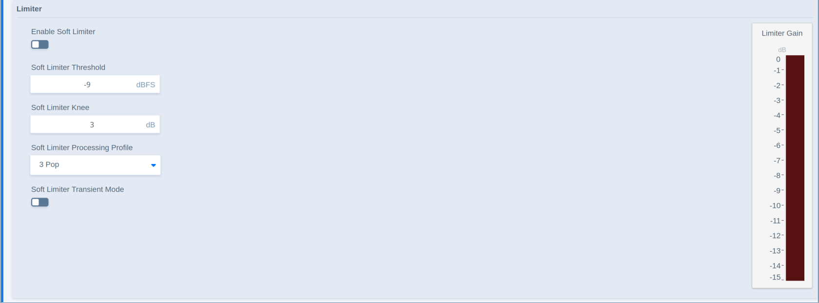
|
Parameter - Limiter |
Description |
|---|---|
|
Enable Soft Limiter Enable |
Enables or disables the soft limiter stage. |
|
Soft Limiter Threshold |
Sets the level at which the soft limiter becomes active. |
|
Soft Limiter Knee |
Controls the response curve’s transition into soft limiting. |
|
Soft Limiter Processing Profile |
Selects the processing profile for the soft limiter. |
|
Soft Limiter Transient Mode |
Selects the transient behavior used by the soft limiter. Transient mode speeds up attack to catch transients more efficiently. |
Related Processors
-
Voice Processing Channel Strip
Equalizer
Applicability
This description applies to the Mono, Stereo, Surround, and Immersive versions of the Equalizer module.
Overview
Equalizer is a module for adjusting the frequency response of the signal. It provides multiple filter bands that can be used for tonal correction, sound shaping, or compensation.
Processing Principle
Each EQ band applies the selected filter type at the configured frequency, gain, and Q factor. Grouping controls whether channels are adjusted together or independently. The control window of the Equalizer can be switched between Graph View and Grid View. The parameters for filter control are the same.
Parameters
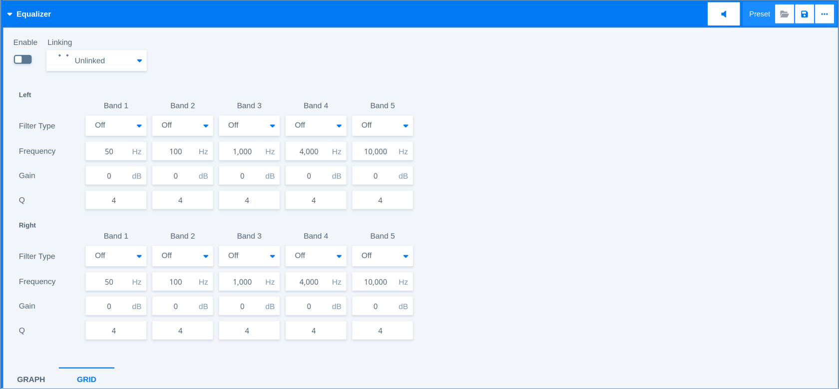
|
Parameter - General |
Description |
|---|---|
|
Enable |
Enables or disables the equalizer stage. |
|
Linking |
Controls how channel parameters are linked for filter adjustments. |
|
Filter Types |
Peak 1 (wider bell curve), Peak 2 (narrower bell type), Lo Shelf (low shelf filter with no resonance), Hi Shelf (high shelf filter with no resonance), Lo Cut (12 dB/octave high-pass), Hi Cut (12 dB/octave low-pass). |
|
Parameter - Equalizer Bands |
Description |
|
Band 1 Filter Type |
Selects the filter type for band 1. |
|
Band 1 Frequency |
Sets the operating frequency for band 1. |
|
Band 1 Gain |
Adjusts the gain for band 1. |
|
Band 1 Q Factor |
Sets the quality (inverse bandwidth) or selectivity for band 1. |
|
Band 2 Filter Type |
Selects the filter type for band 2. |
|
Band 2 Frequency |
Sets the operating frequency for band 2. |
|
Band 2 Gain |
Adjusts the gain for band 2. |
|
Band 2 Q Factor |
Sets the quality (inverse bandwidth) or selectivity for band 2. |
|
Band 3 Filter Type |
Selects the filter type for band 3. |
|
Band 3 Frequency |
Sets the operating frequency for band 3. |
|
Band 3 Gain |
Adjusts the gain for band 3. |
|
Band 3 Q Factor |
Sets the quality (inverse bandwidth) or selectivity for band 3. |
|
Band 4 Filter Type |
Selects the filter type for band 4. |
|
Band 4 Frequency |
Sets the operating frequency for band 4. |
|
Band 4 Gain |
Adjusts the gain for band 4. |
|
Band 4 Q Factor |
Sets the quality (inverse bandwidth) or selectivity for band 4. |
|
Band 5 Filter Type |
Selects the filter type for band 5. |
|
Band 5 Frequency |
Sets the operating frequency for band 5. |
|
Band 5 Gain |
Adjusts the gain for band 5. |
|
Band 5 Q Factor |
Sets the quality (inverse bandwidth) or selectivity for band 5. |
Related Processors
-
Automixer - 5.1
-
Automixer - Stereo
-
FM Conditioner Channel Strip - Stereo
-
Monitoring Controller - 7.1.4
-
Program + Spectral Processing Channel Strip - 5.1
-
Program + Spectral Processing Channel Strip - Stereo
-
Program Processing Channel Strip - 7.1.4
-
Program Processing Channel Strip - 7.1.4 (+Upmix)
-
Voice Processing Channel Strip - Mono
-
Voice Processing Channel Strip - Stereo
Expander
Applicability
This description applies to the Stereo, Surround, and Immersive versions of the Expander module.
Overview
Expander is a module for reducing low-level signal components (downward expansion). It can be used to reduce background noise, ambience, or unwanted low-level content before compression and loudness processing. A gating mode (full cut) is available.
Processing Principle
The module applies gain reduction when the signal falls below the configured threshold. The range parameter limits the maximum amount of reduction, and the processing profile controls the response behavior. In gate mode the level gets fully cut.
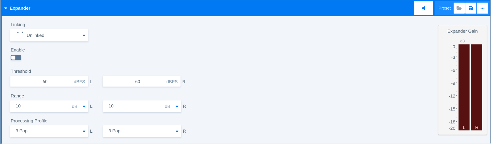
Parameters
|
Parameter |
Description |
|
Linking |
Controls how channel paramters are linked and the side chain audio is grouped for expansion. |
|
Enable |
Enables or disables the expander stage. |
|
Threshold |
Sets the level below which expansion becomes active. |
|
Range |
Limits the maximum gain reduction applied by the expander. In gate mode the level gets fully cut. |
|
Processing Profile |
Selects the expander processing profile. The profile represent faster or slower timing reaction. |
Related Processors
-
FM ConditionerChannel Strip - Stereo
-
Program Processing Channel Strip - 5.1
-
Program Processing Channel Strip - Stereo
-
Program Processing Channel Strip - 7.1.4
-
Program Processing Channel Strip - 7.1.4 (+Upmix)
Fail Over
Applicability
This description applies to the fail-over modules used in stereo program inputs of several Processors when the Upmix option is not available.
Overview
Fail Over is a module for switching from a primary source to a backup or alternate source when the selected failure conditions are met.
Processing Principle
The module monitors the signal according to the selected mode, side-chain filter, threshold, and wait time. When the failure condition persists long enough, the module switches to the alternate path. The return behavior controls how the module switches back when the original source becomes valid again.
Parameters
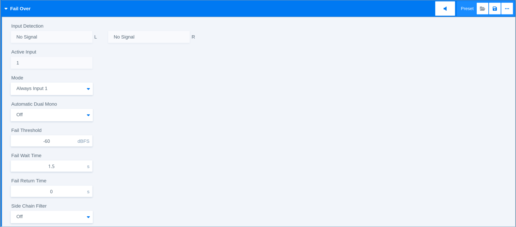
|
Parameter |
Description |
|
Input Detection |
Shows signal action separately for both inputs. |
|
Active Input |
Shows the selected input. |
|
Mode |
Selects the fail-over operating mode. It can be used to set the fail over as a static switch. In auto mode it can be used which of the two inputs is used as a primary (main) source. |
|
Auto Dual Mono |
Controls automatic dual-mono handling. Dual Mono will copy the missing left or right input channel onto the respective channel to achieve dual mono operation in case of missing stereo. |
|
Fail Threshold |
Sets the signal threshold level used to detect a failure condition. |
|
Fail Wait |
Sets how long the fail condition must persist before switching. |
|
Fail Return |
Controls the wait time before the module returns to the primary source after recovery. |
|
Side-chain Filter |
Selects or enables filtering for the signal used to detect failure conditions. It can be used to remove for example 50 Hz or 60 Hz humming from keeping the fail over from switching channels. |
Related Processors
-
Automixer - Stereo
-
FM Conditioner Channel Strip - Stereo
-
Fail Over - Stereo (+Conditioner)
-
Program Processing Channel Strip - Stereo
FM Conditioner
Applicability
This description applies to the Stereo version of the FM Conditioner module.
Overview
FM Conditioner is a module for preparing a stereo program signal for FM transmission-related workflows. It includes operating level, pre-emphasis, low-pass filtering, true peak limiting, and MPX-related controls.
Processing Principle
The module conditions the stereo signal according to FM-related level and deviation targets. It can apply pre-emphasis limiting, true-peak limiting, and control the MPX output.
"A Cool Setup Guide To Optimized Deviation"
FM radio broadcast is not only about audio. Instead the signal consists of different services that share the ‘space’ available on the FM carrier. A typical stereo radio signal spectrum may look like this
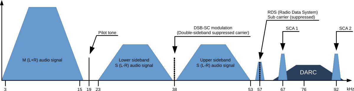

Typical FM modulation spectrum
-
Mono audio signal (M=L+R) - 30 Hz to 15 kHz base band
-
Stereo pilot tone at 19 kHz - approximately 9 % of 75 kHz deviation
-
Stereo audio signal (S=L-R) - 30 Hz to 15 kHz base band
-
DSB-SC carrier - Double-sideband suppressed carrier
-
RDS signal - Radio Data Signal at 1 187,5 Bit/s
-
DARC signal - Data Radio Channel at about 16 000 Bit/s
-
SCA signal - 14 kHz (narrow) or 26 kHz (wide) bandwidth for auxiliary audio services
To calculate the overall MPX Power the power spectrum of all consisting signals needs to be considered.
Please note that within the FM Conditioner Web UI, only RDS and SCA Deviation can be set as additional services. As SCA and DARC normally cannot be used simultaneously due to their overlapping frequency bands, the SCA Deviation parameter can also be used for DARC. To calculate the overall deviation, all of the services in use must be taken into account to ensure that they do not exceed the modulation limits defined by the ITU (as shown below). After setup, this process happens internally and is not a concern for the FM Conditioner user.
When dealing with processing for FM broadcast, four main parameters come into focus:
-
Deviation Δf of the transmission frequency (carrier) fc
-
MPX Power of the modulating signal (modulator)
-
Pre-Emphasis to enhance the signal-to-noise ratio of FM transmission
-
Baseband bandwidth of all involved services (audio signals and auxiliary data)
ITU-R BS.412
ITU-R BS.412 has standardized the maximum values for these parameters. Broadcasters must comply with these limits to not exceed the planned coverage or interfere with adjacent programs. They are:
-
Maximum peak deviation of +75 kHz
-
Maximum MPX Power of 0 dBr
-
A typical audio baseband cutoff at 15 kHz to ensure undisturbed transmission of the 19 kHz stereo pilot tone
-
For mono operation a typical audio baseband bandwidth of 17.5 kHz is utilized (no pilot tone is necessary)
Calibration
MPX Power is measured at random intervals of 60 seconds. An MPX Power level of 0 dBr should be equivalent to the modulation power of a stationary sine signal that induces a deviation of +19 kHz. A stimulus frequency of 500 Hz is recommended.
The tasks required to comply with this rule may sound 'simple' on the surface: take your pocket power measurement instrument, connect it to your readily accessible reference antenna, tune it to your transmitter, and take measurements. Then, adjust the relevant audio parameters if necessary. However, as this approach is not applicable for studio equipment, we must calculate MPX Power before modulation and then translate it to the studio output. To ensure precise calculations, all technical equipment must be gain-matched and calibrated.

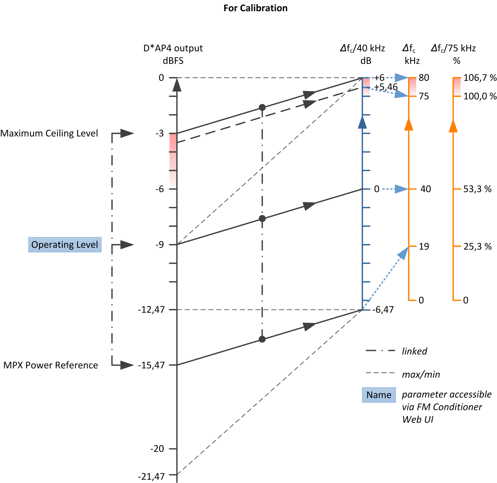
Relation of audio levels and modulation deviation during calibration
The crucial step in calibration is setting the Operating Level. A stationary sine signal at this level should induce a 40 kHz deviation in the FM carrier. If the input level (at the FM HPA or uplink line) for this reference modulation is known, simply configure the Operating Level in the FM Conditioner accordingly. This is applicable in most installations.
In many stations, the reference level for a 500 Hz tone is +6 dBu (analog) or -9 dBFS (digital). It may be designated as the operating level and defined at 0 dB relative (as displayed on a peak level meter). However, please exercise caution with this type of reference level scale, as this analog operating level of 0 dBr is not the same as 0 dBr MPX Power.
If the reference modulation is unknown, you need to apply a sine test tone and measure the frequency deviation of the FM carrier over the air. Start with a generator level of -9 dBFS and adjust this value until you achieve a 40 kHz deviation. It's important to note that any processing in the signal chain between the generator and FM HPA must be bypassed during calibration. The calibration process should be carried out without considering any processing, additional services, or pilot signals.
If the Reference Level of your setup differs from -9 dBFS, you can use the Setup Gain of the FM Conditioner for level matching.
The second step of calibration involves configuring the values for the Pilot Tone, RDS, and SCA (DARC) Deviation. The required values depend on the settings of the respective encoders. Please refer to their manuals.
After completing the calibration process, the FM Conditioner will display the available audio headroom.
Here is an example with an assumed deviation of ~ 12 % of 75 kHz for the extra services:
20*log (75 kHz – 8.8 kHz) / 40 kHz = 4,4 dB
Or -4.6 dBFS
Operation
All calculation is performed internally and updates automatically whenever any of the involved parameters change. The resulting value is referred to as the 'Ceiling.' It's essential to understand that the Ceiling is calculated with the Pre-Emphasis filtering of the FM transmitter included. Therefore, the wideband true peak level of the audio signal before Pre-Emphasis must be lower. To better grasp this concept, you can refer to the level relation diagram:
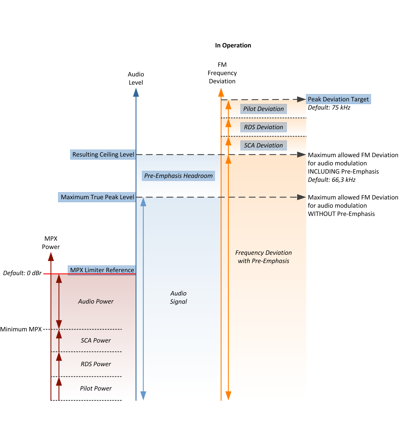

Relation of audio levels and modulation deviation in operation
Pre-Emphasis
Pre-Emphasis is a filtering system in which higher frequencies are boosted by a shelving filter at the transmission stage and conversely reduced at the receiver end. The Pre-Emphasis filter employs a time constant of 50 µs (or 75 µs in the USA), resulting in a 10 dB gain at 10 kHz. This process significantly improves the signal-to-noise ratio. However, as the increased high-frequency energy contributes to the MPX Power, it must be taken into account within the FM Conditioner.
There are two mechanisms to manage Pre-Emphasis. First, a Pre-Emphasis Headroom parameter reduces the maximum wideband level by lowering the true peak limiter threshold. This results in lower overall audio levels but enhanced high-frequency transparency. Second, a process called Pre-Emphasis Limiter dynamically reduces the high-frequency component of the audio signal, creating 'space' for the additional Pre-Emphasis shelving. The Pre-Emphasis Limiter is always active and prevents high-frequency overmodulation. To lessen its impact, the Pre-Emphasis Headroom should be increased. The Pre-Emphasis Limiter is based on sophisticated dynamic filter algorithms, well-known from the state-of-the-art Jünger Audio De-Esser.
It's important to note that very short transients may not be fully mitigated by the Pre-Emphasis Limiter. Nevertheless, this is a fundamental aspect and has no practical significance for FM transmission.
True Peak Limiter
The Maximum True Peak value cannot be manually set by the user since it is automatically calculated and set to the Ceiling Level minus the Pre-Emphasis Headroom. When there's no Pre-Emphasis Headroom, the Maximum True Peak equals the Ceiling.
The MPX Limiter algorithm
The most crucial component of the FM Conditioner processor is undoubtedly the MPX Limiter. Since MPX Power is a value calculated over one minute of integration time, limiting can be a highly intricate task. In theory, a 60-second look-ahead time may seem appropriate, but it's not practically feasible for a real-time processor. Therefore, the Jünger Audio MPX Limiter employs a complex prediction algorithm that adapts to the incoming signal structure. Nevertheless, the limiter reference level remains an absolute brickwall threshold and is considered inviolable. In the event of an 'emergency,' the MPX Limiter will drastically reduce the signal level to prevent any threshold violation. The MPX Limiter in the FM Conditioner can be considered the most effective MPX brickwall limiter available today.
Please be aware that the MPX Limiter Reference can, of course, be exceeded when incoming levels are high and the MPX Limiter has just been activated. According to the measurement principle, it may take up to one minute for the MPX Limiter to stabilize
The MPX Limiter Profile impacts the speed and extent of the process and, consequently, its neutrality toward incoming sound quality. When using softer settings, the system requires a buffer zone between the MPX Limiter reference and the measured MPX of the audio signal. Although this buffer zone is always very small, with harder settings, it becomes even smaller, allowing for higher MPX Power transmission. The optimal setting depends on the type and style of the program being broadcast.
Parameters
General and Filtering
|
Parameter - General and Filtering |
Description |
|
FM Conditioner Enable |
Enables or disables the FM Conditioner stage. |
|
Operating Level |
Sets the operating level used by the FM conditioning process. |
|
Setup Gain |
Adjusts the setup gain before FM conditioning. |
|
Low-pass Filter Enable |
Enables or disables the low-pass filter the protects the pilote tone from interference with the audio signal. |
|
Pre-emphasis |
Selects or configures the pre-emphasis behavior. |
|
Pre-emphasis Headroom |
Sets the headroom used for pre-emphasis processing. |
|
True Peak Limiter Profile |
Selects the true peak limiter timing profile used by the FM conditioning path. |
MPX and Deviation
|
Parameter - MPX and Deviation |
Description |
|
MPX Enable |
Enables or disables MPX limiting. |
|
MPX Limiter Profile |
Selects the MPX limiter timing profile. |
|
MPX Reference |
Sets the MPX reference level. |
|
Peak Deviation Target |
Sets the target peak deviation. |
|
Pilot Deviation |
Sets the pilot deviation value. |
|
RDS Deviation |
Sets the RDS deviation value. |
|
SCA Deviation |
Sets the SCA deviation value. |
|
Reset Max |
Resets maximum value tracking in the meters when applied or when a preset is loaded. |
Metering
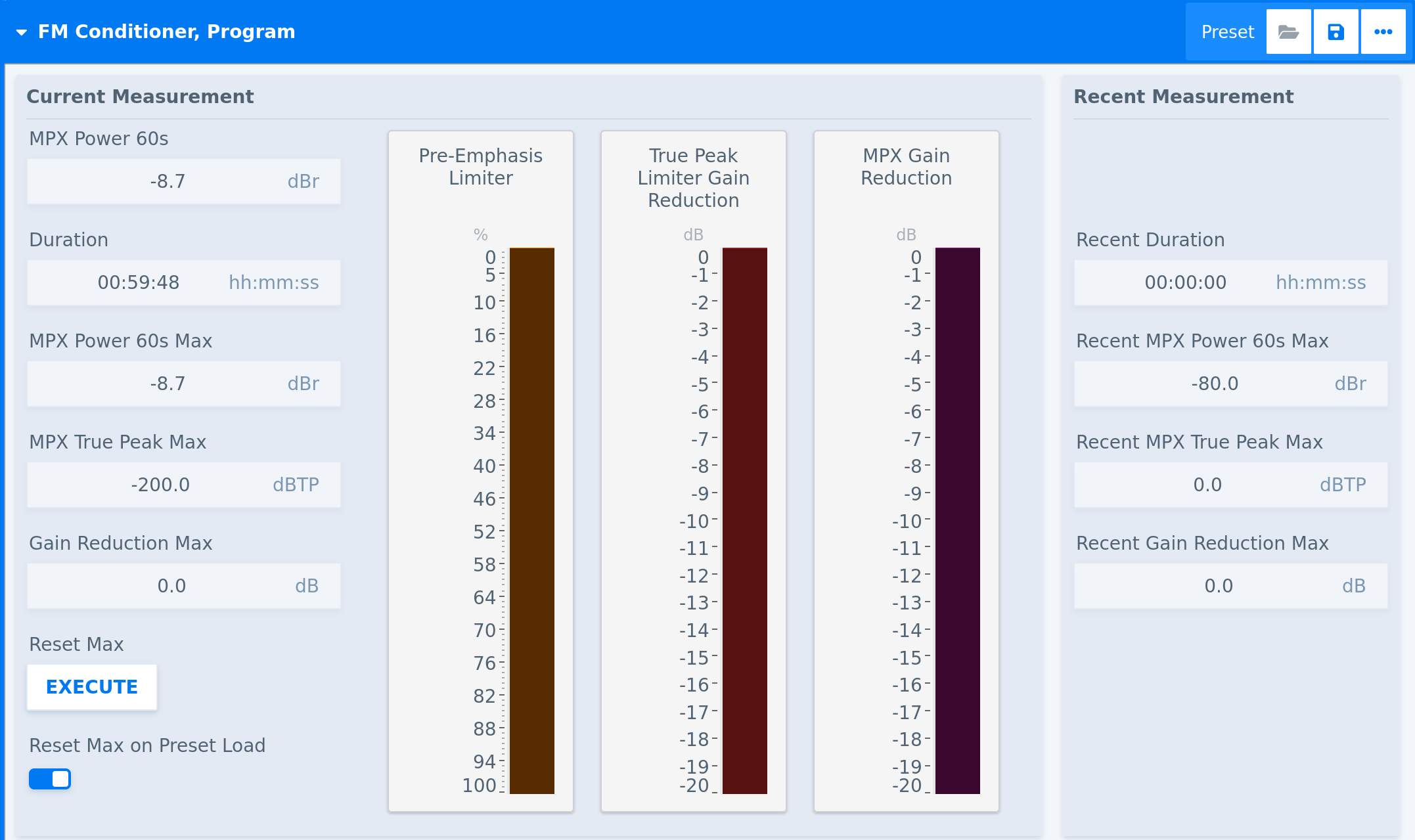
|
Parameter - Measurement |
Description |
| Reset Max |
Triggers the reset of the Current Measurement cycle and writes its values in the Recent Measurement section on the right-hand side of the meters. |
|
Reset Max on Preset Load |
Triggers the aforementioned reset when a preset is loaded. |
Related Processors
-
FM Conditioner Channel Strip - Stereo
Input Conditioner
Applicability
This description applies to the Mono, Stereo, Surround, and Immersive versions of the Input Conditioner module.
Overview
Input Conditioner is a module for basic preparation of an input signal before further processing. It provides level, mute, polarity, filter, mono, delay, and grouping controls.
Processing Principle
The module adjusts the incoming signal before it enters the main processing chain. It can apply per-channel and master gain, channel mute and polarity handling, high-pass and low-pass filtering, and delay. Coarse and fine delay add up to a total delay value.
Parameters
Level and Channel Control
|
Parameter - Level and Channel Control |
Description |
|
Enable |
Enables or disables the Input Conditioner stage. |
|
Grouping |
Controls how channels are linked or grouped. |
|
Master Gain |
Adjusts the overall gain of the conditioned input signal for all channels. It can be used as a master fader, for example in combination with an automation system or a physical fader via a control protocol. |
|
Gain |
Adjusts the gain of an individual channel (subject to linking settings). |
|
Mute |
Mutes an individual channel (subject to linking settings). |
|
Mono |
Controls mono handling for the input path. |
|
Polarity |
Inverts or restores the polarity of an input channel. |
Filtering and Delay
|
Parameter - Filtering and Delay |
Description |
|
HPF |
Controls the frequency of a high-pass filter. |
|
LPF |
Controls the frequency of a low-pass filter. |
|
Delay Coarse |
Sets the coarse input delay amount in milliseconds. |
|
Delay Fine |
Sets the fine input delay amount in samples. |
Related Processors
-
Automixer - 5.1
-
Automixer - Stereo
-
FM Conditioner Channel Strip - Stereo
-
Fail Over - Stereo (+Conditioner)
-
Monitoring Controller - 7.1.4
-
Program Processing Channel Strip - 5.1
-
Program Processing Channel Strip - Stereo
-
Program Processing Channel Strip - 7.1.4
-
Program Processing Channel Strip - 7.1.4 (+Upmix)
-
Voice Over Mixer - Stereo
-
Voice Over Mixer - Surround
-
Voice Processing Channel Strip - Mono
-
Voice Processing Channel Strip - Stereo
Input Leveler
Level Magic
Applicability
This description applies to the Mono, Stereo, Surround, and Immersive versions of the Level Magic module.
Depending on the Processor, Level Magic may be used for a complete program path, a voice path, a downmix path, or an output processing path. In block diagrams and Processor layouts, the module may appear as Level Magic, LM, or Leveler, depending on its role in the signal chain.
Overview
Level Magic is a module for automatic loudness control with optional true peak limiting. It is used to keep the processed signal close to a controlled loudness target level while preserving a natural-sounding result.
The module combines long-term level control with short-term transient processing. In many Processors, it is placed near the end of the signal chain, after equalization and dynamics processing and before output conditioning or output metering. Its output signal can be considered “broadcast ready”.
Processing Principle
The leveler stage analyzes the input signal and applies automatic gain control to move the signal toward the configured loudness target. The amount and timing of the gain correction are controlled by the leveler settings. The transient processor controls short-term signal changes that may occur during loudness processing. It can help the module react to sudden level changes without relying only on long-term gain control.
The limiter stage controls output peaks and helps prevent the processed signal from exceeding the configured maximum true peak level.
Parameters
Leveler
|
Parameter - Leveler |
Description |
|
Enable Leveler |
Enables or disables the Level Magic loudness control stage. |
|
Input Gain |
Adjusts the signal level before loudness processing. |
|
Mode |
Selects the loudness processing mode used by the module. |
|
Processing Profile |
Selects the processing profile used for transient handling in the leveler stage. |
|
Loudness Target |
Sets the target loudness level for automatic level control. |
|
Leveler Time |
Sets the response time of the automatic leveler. |
|
Leveler Max Gain |
Limits the maximum positive gain applied by the leveler. |
|
Leveler Freeze Level |
Sets the level below which the current leveler gain can be held or frozen. |
|
Transient Processor Max Gain |
Limits the maximum gain applied by the transient processor. |
|
Transient Processor Response |
Sets the response behavior of the transient processor. |
|
AGC Recovery |
Selects how the automatic gain control recovers after gain correction. |
|
Processing Threshold |
Sets the input level threshold used to determine when loudness processing is active. |
|
Below Threshold Mode |
Controls how the module behaves when the signal is below the processing threshold. |
|
Initial Dynamic Gain |
Sets the initial dynamic gain value used when processing starts or is initialized. |
|
Clear Processing History |
Clears the internal loudness analysis history and restarts processing from the current signal state. |
Limiter
|
Parameter - Limiter |
Description |
|
Limiter Enable |
Enables or disables the limiter stage. |
|
Limiter Processing Profile |
Selects the limiter processing profile. |
|
Limiter Max True Peak |
Sets the maximum true peak level for the limiter output. |
|
Limiter Low Latency Mode |
Enables or disables low-latency limiter operation. |
Related Processors
Level Magic is used in the following Processors:
-
Automixer - Surround
-
Automixer - Stereo
-
FM Conditioner Channel Strip - Stereo
-
Program Processing Channel Strip - Stereo
-
Program Processing Channel Strip - Surround
-
Program Processing Channel Strip - Immersive
-
Voice Over Mixer - Stereo
-
Voice Over Mixer - Surround
-
Voice Processing Channel Strip - Mono
-
Voice Processing Channel Strip - Stereo
Limiter / Failsafe Limiter
Loudness Measurement
Applicability
This description applies to the Stereo, Surround, and Immersive versions of the Loudness Measurement module.
Overview
Loudness Measurement is a module for measuring loudness and true peak values of program, monitor, or output paths. It is used for monitoring loudness distribution before or after processing stages.
Processing Principle
The module measures loudness over time and provides controls for running, pausing, and resetting the measurement state and its maximum values.
Parameters
|
Parameter |
Description |
|
Measurement State |
Controls the current run or pause state of the loudness measurement. |
|
Run/Pause |
Sets the measurement to run or pause when applied or when a preset is loaded. |
|
Reset |
Resets the loudness measurement when applied or when a preset is loaded. |
|
Reset Max |
Resets the stored maximum loudness and peak values when applied or when a preset is loaded. |
Related Processors
-
Automixer
-
FM Conditioner Channel Strip
-
MPEG-H 3D Audio Renderer
-
Program Processing Channel Strip
-
S-ADM Dolby Renderer
-
Voice Over Mixer
Monitoring Controller
Applicability
This description applies to the Monitoring Controller module in the Monitoring Controller processor.
Overview
The Monitoring Controller module is used for basic monitoring operation like controlling monitor volume, mute, dim and solo.
Processing Principle
The module applies monitor control functions to the monitoring path. It can adjust listening level, apply dim, mute or solo to selected channels or speaker groups. The module can be loaded in two configurations:
-
Setup view with all parameters visible
-
Operator view with only parameters visible that are necessary in daily operation
The Operator View can be uncoupled from the main windows and separately used on touch screen or mobile devices.
Parameters
Volume and Dim
|
Parameter - Volume and Dim |
Description |
|
Volume |
Sets the monitor listening level. |
|
Reference Volume |
Moves the monitor level to the reference volume when triggered or when a preset is loaded. |
|
Set Reference Volume |
Sets the monitor listening level to a reference value. |
|
Dim |
Enables or disables volume dimming. |
|
Dim Offset |
Sets the amount of level reduction applied when dim is active. |
Mute and Solo
|
Parameter - Mute and Solo |
Description |
|
Mute |
Mutes selected channels. |
|
Mute All |
Mutes all monitor outputs. |
|
Mute Clear |
Clears active mute states when triggered or when a preset is loaded. |
|
Mute Middle Level Speakers |
Mutes the middle-level speaker group. This group consists of L, R, C, LSS, RSS (in 5.1) and LRS, RRS (in 7.1). |
|
Mute Top Level Speakers |
Mutes the top-level speaker group. This group consists of TFL, TFR, TRL and TRR |
|
Solo |
Solos selected channels. |
|
Solo Mode |
Selects the solo operating mode. Modes are: Solo in Place, Solo to LR and Solo to Center. Depending on the selected mode a soloed channel will be isolated (all others are muted) and either stay in place or be moved to the selected loudspeaker position. |
|
Solo Defeat |
Channels in solo defeat will not be muted if another channel is soloed. This is especially helpful for Subwoofers. |
|
Solo Clear |
Clears all active solo states when triggered or when a preset is loaded. |
|
Mono L/R |
Controls mono (L+R) monitoring for the left and right channels. |
Related Processors
-
Monitoring Controller
-
Monitoring Controller - Immersive
MPEG-H Authoring
Applicability
This description applies to the MPEG-H 3D Audio Authoring module.
Overview
MPEG-H 3D Audio Authoring is a module for creating and modifying metadata as well as preparing audio for MPEG-H 3D Audio encoding.
Processing Principle
The module provides the metadata authoring stage and allows for modifying the respective audio channels and objects.
Parameters
Related Processors
-
MPEG-H 3D Audio Authoring
Output Conditioner
Peak Meter
Phase Rotator
Speaker ID
Spectral Signature
Switch
Upmix
Applicability
This description applies to the Surround (up to 5.1) and Immersive (up to 7.1.4) versions of the Auto Upmix module.
The terms Upmix and Auto Upmix are used interchangably.
Overview
Upmix is a module for deriving a higher-channel output format from a lower-channel or partially populated input format. It is used to create surround or immersive program paths from available source signals.
The module can also include source fail-over and surround detection behavior, depending on the Processor in which it is used.
Processing Principle
Upmix analyzes the selected source format and generates the configured target format. It can distribute center, surround, side surround, LFE, and height-related components according to the selected upmix mode and related balance settings.
Additional detection and fail-over parameters control how the module reacts to missing or unsuitable input signals.
Parameters
Format and Mode
|
Parameter - Format and Mode |
Description |
|
Source Format |
Selects the source channel format used for upmixing. |
|
Target Format |
Selects the target channel format generated by the module. |
|
Upmix Mode |
Selects the upmix processing mode. |
|
Surround Output Select |
Selects which surround output components are generated or used. |
Upmix Balance
|
Parameter - Upmix Balance |
Description |
|
Center Gain |
Adjusts the generated or routed center channel level. |
|
Upmix Center Divergence |
Controls how center content is distributed during upmixing. |
|
Surround Gain |
Adjusts the generated surround channel level. |
|
Side Surround Gain (only version 7.1 and 7.1.4) |
Adjusts the generated side surround channel level. |
|
Vertical Balance (only version 5.1.4 and 7.1.4) |
Controls the balance between lower-layer and upper-layer components in immersive upmixing. |
|
Top Layer Crossover Frequency (only version 5.1.4 and 7.1.4) |
Sets the crossover frequency used for top-layer processing. |
|
Top Layer Crossover Direct Mix (only version 5.1.4 and 7.1.4) |
Controls direct signal mixing into the top-layer crossover path. |
LFE and Center Replacement
|
Parameter - LFE and Center Replacement |
Description |
|
Upmix LFE Enable |
Enables or disables generated LFE processing. |
|
Upmix LFE Gain |
Adjusts the generated LFE level. |
|
Upmix LFE Cutoff |
Sets the cutoff frequency for generated LFE content. |
|
Upmix LFE Effect Gate Threshold |
Sets the threshold used for LFE effect gating. |
|
Center Replacement |
Enables or configures center replacement behavior. |
|
Center Replacement Center Divergence |
Controls how replacement center content is distributed. |
Detection and Fail-over
|
Parameter - Detection and Fail-over |
Description |
|
Surround Detection Channels |
Selects the channels used for surround detection. |
|
Surround Detection Threshold |
Sets the threshold for detecting surround content. |
|
Surround Detection Wait |
Sets the wait time before surround detection changes state. |
|
Fail-over Side-chain Filter |
Selects or enables filtering for fail-over detection. |
|
Fail-over Fail Threshold |
Sets the signal threshold used to detect a failure condition. |
|
Fail-over Fail Wait |
Sets how long the fail condition must persist before switching. |
|
Fail-over Fail Return |
Controls how the module returns after a failed source becomes valid again. |
Related Processors
-
Automixer - 5.1
-
Program + Spectral Processing Channel Strip - 5.1
-
Program Processing Channel Strip - 7.1.4 (+Upmix)
Mixer
MPEG-H 3D Audio Renderer
Applicability
This description applies to the MPEG-H 3D Audio Renderer module.
Overview
MPEG-H 3D Audio Renderer is a module for rendering MPEG-H 3D Audio content according to its metadata and user input to a selected monitoring or output target.
Processing Principle
The module uses the selected metadata source to render the incoming audio signals. Users can select the presentation, user data and output format either for quality checking the signal or creating channel based downmixes for further processing or distribution.
Parameters
Rendering and Metadata
|
Parameter - Rendering and Metadata |
Description |
|
Metadata Source |
Selects the metadata source used by the renderer. |
|
Rendering Target |
Selects the target channel layout for the rendering. |
|
DRC Effect |
Selects the dynamic range control effect used during rendering. |
|
Loudness Normalization Target |
Sets the loudness normalization target used by the renderer. |
|
Preferred Accessibility |
Selects the preferred accessibility option. |
|
Preferred Language |
Selects the preferred language option. |
Interactive Elements
|
Parameter - Interactivity Elements |
Description |
|
OSD Active Preset |
Selects the active OSD preset. |
|
OSD Element Azimuth |
Sets or displays the azimuth position of an OSD element. |
|
OSD Element Elevation |
Sets or displays the elevation position of an OSD element. |
|
OSD Element Gain |
Adjusts the gain of an OSD element. |
|
OSD Element Muted |
Mutes or unmutes an OSD element. |
|
OSD Switch Group Active Element |
Selects the active element in an OSD switch group. |
|
Reset Max Execution Time |
Resets maximum execution time tracking when triggered or when a preset is loaded. |
|
Reset Metadata Decoding Errors |
Resets metadata decoding error counters when triggered or when a preset is loaded. |
Related Processors
-
MPEG-H 3D Audio Renderer
Routing
Routing
The routing view is organized as a list-based connection system. Sources are shown on the left, destinations are shown on the right, and the connections between them are created as rows in the center.
Select any source on the left-hand side and a free destination on the right-hand side.
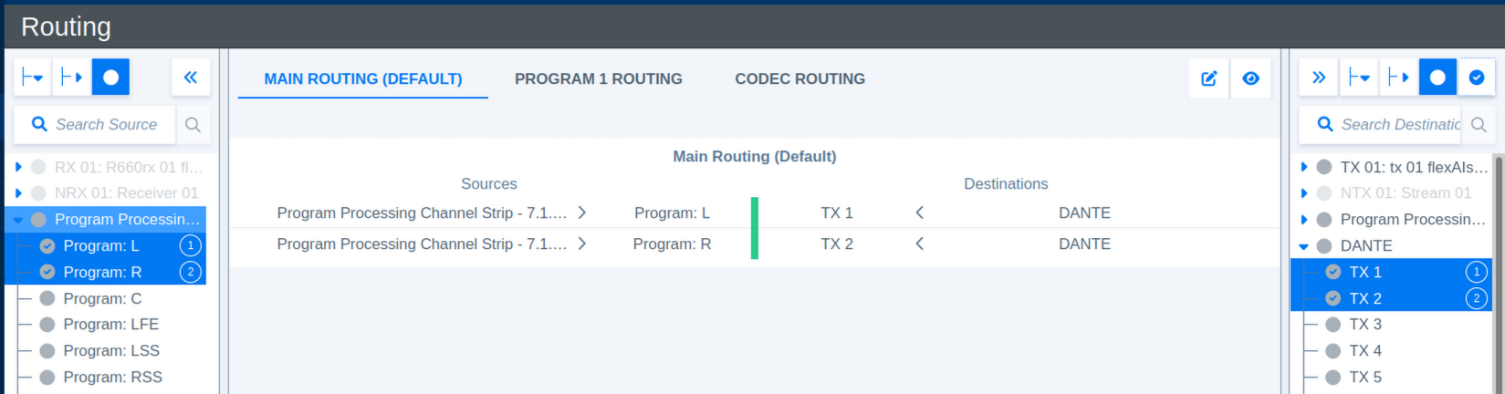
To connect the selected routing click on Link (New) at the bottom of the center section.

Any source can be used for routing with no limitations, destinations can only be used once. Connections will be established in the order of the ascending selection. This order is marked with ascending numbers on each selected source and destination.
Several shortcuts are available for managing routings:
- Holding CTRL while selecting sources or destinations will add them to the selection.
- Holding SHIFT enables selecting multiple adjacent sources or destination in a selection.
- Keep the mouse cursor steady over one of the icons to see a short description of its function.
After selecting a connection multiple tools are available for modifying sources, destinations and other fuctionality.
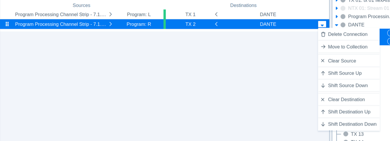
Routings can be managed in separate Routing Collections.
Each Routing Collection can hold its own Presets.
Routing Collections
Routing Collections allow you to organize routing connections into separate groups. Each collection can have its own presets, making it easier to manage different sets of connections for different workflows, signal groups, or operating scenarios.
The available collections are shown at the top of the routing view. Select a collection name to display and manage the connections assigned to that collection.
Use the icons in the upper-right corner of the routing view to manage collections and change the displayed connection view.
The Edit icon opens the collection menu. From this menu, you can add a new collection, rename an existing collection, or delete a collection.
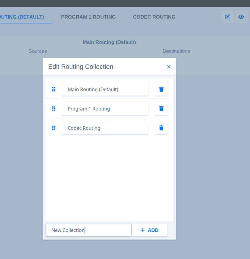
The Eye icon switches the view between the selected collection and all available connections. The currently selected collection is highlighted and underlined in the collection bar.
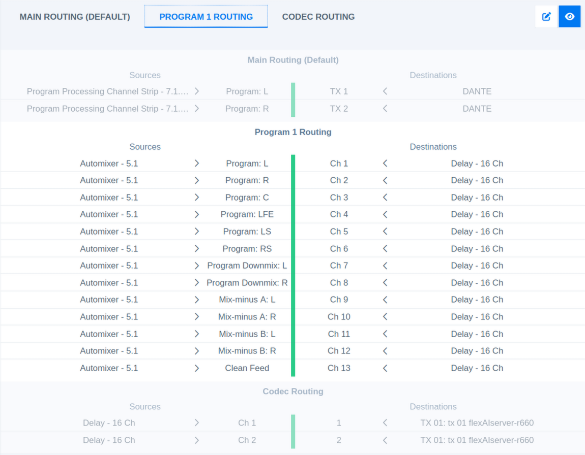
Each Routing Collection has its individual set of presets.
Routing Presets
Presets can be managed by clicking on the Preset icons:

| Parameter | Function |
| File Icon | Open the Load Preset dialog |
| Floppy Disc Icon | Open the Save Preset dialog |
| Three Dots Icon | Open more dialogs (Preset Operations), mainly used to open the Delete Preset dialog |
Save Presets
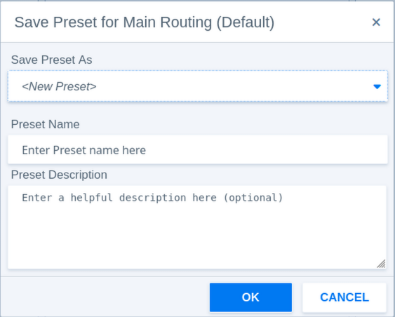
| Parameter - Save Preset | Function |
| Save Preset As | Select to create a new preset or overwrite an existing preset. |
| Preset Name | Enter a preset name here. |
| Preset Description | Optionally a description can be added to help identifying presets. |
Load Presets
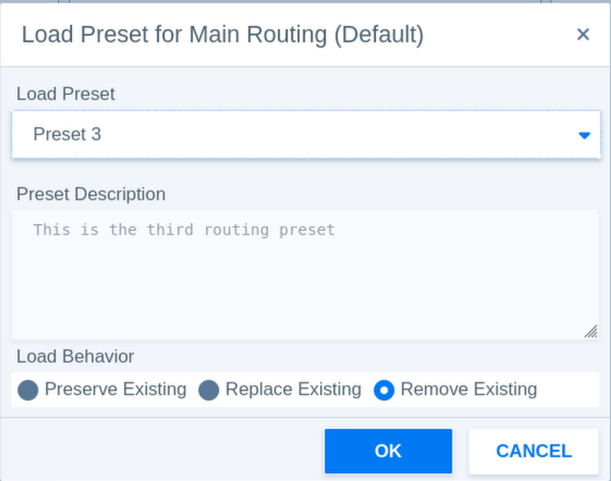
| Parameter - Load Preset | Function |
| Load Preset | Select the preset to load. |
| Preset Description | The description helps identifying presets. |
| Load Behaviour | Decides what happens to existing routings. |
| Preserve Existing | Routings in the preset will be added to the existing routings. This might cause conflicts when destinations are used in multiple connections. |
| Replace Existing | Replaces routings with the same destinations only. |
| Remove Existing | Removes all existing routings and creates new routing connections from the preset values. |
Preset Operations (Delete Presets)
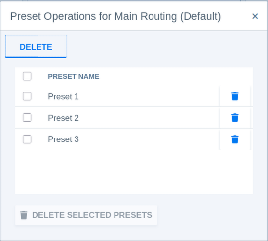
| Parameter - Delete Preset | Function |
| Select Preset | Select the preset(s) to delete. |
| Bin Icon | Delete individual presets. |
| Delete Selected Presets | Delete all selected presets. |
Interfaces
Audio over IP - Setup
The AoIP section under Interfaces provides the configuration and status information for Audio over IP operation.
Important - IGMP Snooping must be enabled on all switch ports connected to flexAI systems. Otherwise, forwarded multicast traffic may stress the connected system.
Expand AoIP in the Interfaces menu and select Setup.
Note - Some AoIP parameters are only visible when **Show Expert Settings** is enabled. Enable this option to display all parameters described in this section.
The page is divided into several sections for general AoIP configuration, network interfaces, synchronization, Livewire, NMOS, receiver settings, and sender settings.
Changes to some low-level AoIP settings may temporarily interrupt active AoIP streams. Where this applies, a corresponding message is shown on the page.
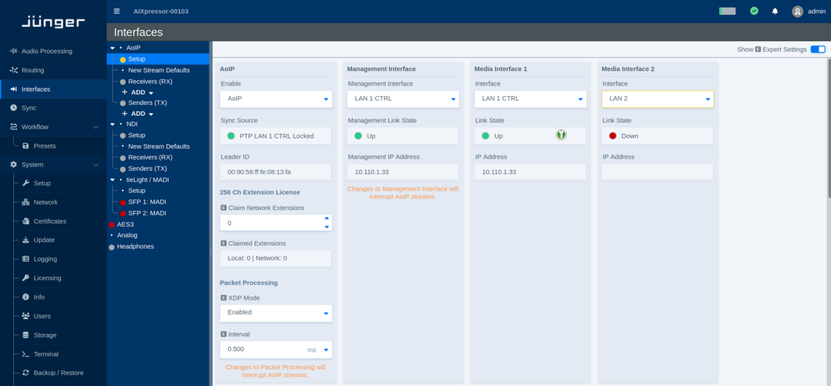
AoIP
This section controls the general AoIP operation and shows the current synchronization status.
| Parameter | Values | Default | Description |
|---|---|---|---|
| Enable | Available AoIP modes / Disabled | - | Enables or disables Audio over IP operation. |
| Sync Source | Status | - | Shows the synchronization source currently used for AoIP and whether the clock is locked. |
| Leader ID | Status | - | Shows the identifier of the PTP Leader Clock currently providing synchronization on the network. |
Channel Extension License
Additional licensed AoIP channel capacity can be made available locally or through network licensing.
| Parameter | Values | Default | Description |
|---|---|---|---|
| Claim Network Extensions | Number of extensions | - | Defines how many available channel extension licenses should be claimed from the network. |
| Claimed Extensions | Status | - | Shows the number of channel extensions currently claimed from local and network license sources. |
Packet Processing
These parameters control low-level packet processing for AoIP.
XDP provides highly efficient packet processing close to the network interface, reducing the CPU overhead associated with AoIP traffic. This makes it possible to handle higher packet rates and very small packet times more efficiently.
| Parameter | Values | Default | Description |
|---|---|---|---|
| XDP Mode | Enabled / Disabled | - | Enables or disables XDP-based packet processing for AoIP. |
| Interval | Supported intervals | - | Defines the packet-processing interval. Incoming packets are collected for this period and then passed on for processing as a group. |
Changing packet-processing settings may interrupt active AoIP streams.
Management Interface
The Management Interface is used for AoIP control and management communication.
The **Management Interface** is used for AoIP control and management traffic, including protocols such as **NMOS**. Selecting the correct Management Interface is therefore important, as these services may be restricted to this interface.
| Parameter | Values | Default | Description |
|---|---|---|---|
| Management Interface | Available network interfaces | - | Selects the network interface used for AoIP management communication. |
| Management Link State | Status | - | Shows whether the selected management interface has an active network link. |
| Management IP Address | Status | - | Shows the IP address assigned to the selected management interface. |
Changing the Management Interface may interrupt active AoIP streams.
Media Interfaces
Media Interfaces carry the AoIP media traffic. Up to four Media Interfaces can be configured, depending on the system and its available network interfaces.
All Media Interface sections use the same parameters.
| Parameter | Values | Default | Description |
|---|---|---|---|
| Interface | Available network interfaces / Disabled | - | Selects the network interface used for AoIP media traffic. Select **Disabled** if the Media Interface is not required. |
| Link State | Status | - | Shows the current physical link state of the selected network interface. |
| IP Address | Status | - | Shows the IP address assigned to the selected Media Interface. |
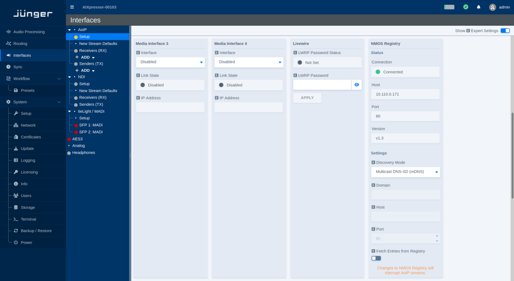
Livewire
The Livewire section provides the password used for Livewire Routing Protocol (LWRP) access.
| Parameter | Values | Default | Description |
|---|---|---|---|
| LWRP Password Status | Status | - | Indicates whether an LWRP password has been configured. |
| LWRP Password | Password | - | Sets the password used for LWRP access. Use the visibility icon to show or hide the entered password. |
| Apply | Button | - | Applies the entered LWRP password. |
NMOS Registry
The NMOS Registry section shows the current NMOS registry connection and provides the corresponding discovery settings.
Status
| Parameter | Values | Default | Description |
|---|---|---|---|
| Connection | Status | - | Shows whether the flexAI system is currently connected to an NMOS Registry. |
| Host | Status | - | Shows the address of the currently used NMOS Registry. |
| Port | Status | - | Shows the port used for the current registry connection. |
| Version | Status | - | Shows the NMOS API version used for the registry connection. |
Settings
| Parameter | Values | Default | Description |
|---|---|---|---|
| Discovery Mode | Available discovery modes | - | Selects how the NMOS Registry is discovered. |
| Domain | Domain name | - | Defines the DNS domain used for registry discovery when required by the selected Discovery Mode. |
| Host | Host name or IP address | - | Defines the NMOS Registry host when manual registry configuration is used. |
| Port | Port number | - | Defines the port of the manually configured NMOS Registry. |
| Fetch Entries from Registry | On / Off | - | Enables retrieval of available entries from the connected NMOS Registry. |
Changing the NMOS Registry configuration may interrupt active AoIP streams.
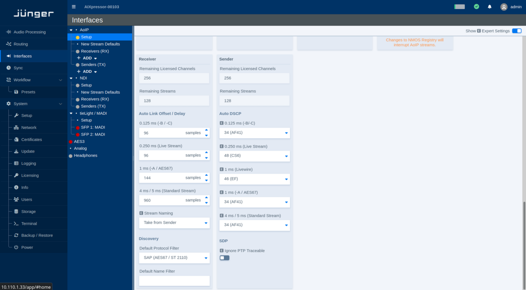
Receiver
The Receiver section shows the remaining receiver capacity and defines default behavior for automatically connected streams and stream discovery.
Capacity
| Parameter | Values | Default | Description |
|---|---|---|---|
| Remaining Licensed Channels | Status | - | Shows the number of licensed receive channels that are currently still available. |
| Remaining Streams | Status | - | Shows the number of additional receiver streams that can currently be created. |
Auto Link Offset / Delay
The Auto Link settings define the receiver delay used when streams are connected automatically. Separate values are provided for the supported stream and packet-time classes.
Auto Link Offset defines the fixed receive/playout delay that is automatically applied when a stream is linked. It provides additional time for network packets to arrive before they are presented to the audio engine, improving tolerance to network jitter and late packets.
A separate offset can be configured for each packet-time class. Once applied, the delay remains constant for streams of that type, so the additional latency is deterministic rather than varying with network conditions.
| Parameter | Values | Default | Description |
|---|---|---|---|
| 0.125 ms (-B / -C) | Delay in samples | - | Defines the Auto Link offset/delay for streams using a 0.125 ms packet time. |
| 0.250 ms (Live Stream) | Delay in samples | - | Defines the Auto Link offset/delay for Live Streams using a 0.250 ms packet time. |
| 1 ms (-A / AES67) | Delay in samples | - | Defines the Auto Link offset/delay for streams using a 1 ms packet time, including AES67 streams. |
| 4 ms / 5 ms (Standard Stream) | Delay in samples | - | Defines the Auto Link offset/delay for Standard Streams using the corresponding packet-time class. |
Higher delay values provide additional buffering at the receiver but also increase the end-to-end audio latency.
Stream Naming
| Parameter | Values | Default | Description |
|---|---|---|---|
| Stream Naming | Available naming modes | - | Defines how automatically connected receiver streams are named. **Take from Sender** uses the name provided by the sending device. |
Discovery
| Parameter | Values | Default | Description |
|---|---|---|---|
| Default Protocol Filter | Available discovery protocols | - | Selects the protocol filter initially applied when discovering streams. Depending on the system configuration, this may include Livewire, SAP for AES67/ST 2110, or NMOS. |
| Default Name Filter | Text | - | Defines an optional name filter applied when displaying discovered streams. Leave the field empty to show streams regardless of their name. |
Sender
The Sender section shows the remaining sender capacity and defines default network parameters for transmitted streams.
Capacity
| Parameter | Values | Default | Description |
|---|---|---|---|
| Remaining Licensed Channels | Status | - | Shows the number of licensed transmit channels that are currently still available. |
| Remaining Streams | Status | - | Shows the number of additional sender streams that can currently be created. |
Auto DSCP
Auto DSCP defines the Differentiated Services Code Point (DSCP) automatically assigned to transmitted AoIP packets for each supported stream type.
| Parameter | Values | Default | Description |
|---|---|---|---|
| 0.125 ms (-B / -C) | DSCP value / class | - | Defines the DSCP marking used for streams with a 0.125 ms packet time. |
| 0.250 ms (Live Stream) | DSCP value / class | - | Defines the DSCP marking used for Live Streams with a 0.250 ms packet time. |
| 1 ms (Livewire) | DSCP value / class | - | Defines the DSCP marking used for Livewire streams with a 1 ms packet time. |
| 1 ms (-A / AES67) | DSCP value / class | - | Defines the DSCP marking used for 1 ms AES67 streams. |
| 4 ms / 5 ms (Standard Stream) | DSCP value / class | - | Defines the DSCP marking used for Standard Streams with the corresponding packet-time class. |
**DSCP (Differentiated Services Code Point)** is a field in the IP header used to classify network traffic for Quality of Service (QoS). Network switches and routers can use this value to prioritize time-critical AoIP packets over less critical traffic.
**Auto DSCP** automatically assigns the appropriate DSCP value according to the selected stream type and packet time. This helps ensure that streams with higher timing requirements receive the intended network priority without having to configure the DSCP value manually.
SDP
| Parameter | Values | Default | Description |
|---|---|---|---|
| Ignore PTP Traceable | On / Off | - | Ignores PTP traceability information when evaluating SDP data. This can be relevant for streams that use absolute timing information referenced to the Unix epoch beginning on January 1, 1970. |
Audio over IP - New Stream Defaults
The New Stream Defaults page defines the initial settings used when new AoIP receiver or sender streams are created.
Changing these settings affects newly created streams only. Existing receivers and senders are not modified.
Select the protocol under Protocol Selection to configure the corresponding defaults. The available parameters may vary depending on the selected protocol.
Protocol
| Parameter | Values | Default | Description |
|---|---|---|---|
| Protocol Selection | Available AoIP protocols | - | Selects the AoIP protocol for which the new-stream defaults are being configured. The available Receiver and Sender parameters may change with the selected protocol. |
SMPTE ST2110 and AES67
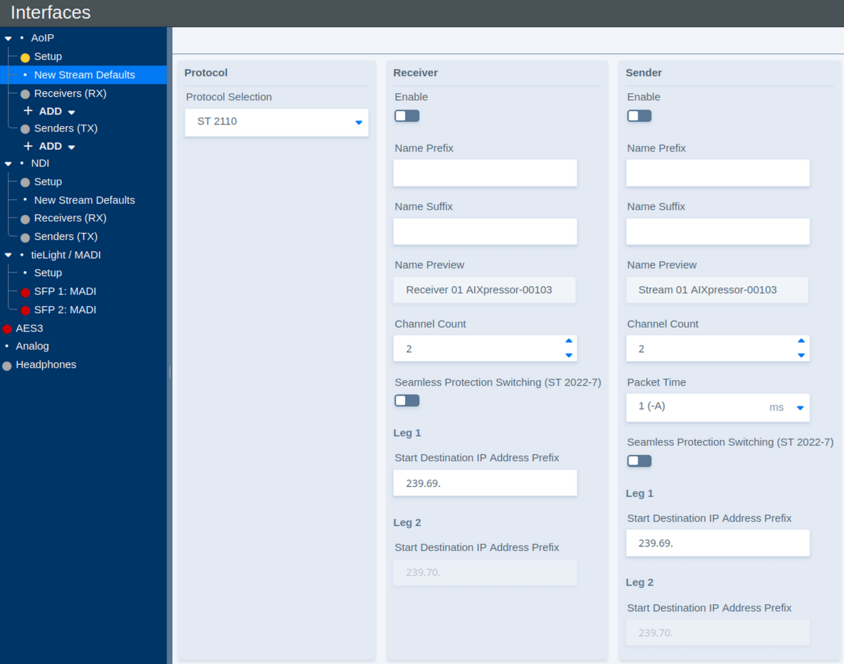
Receiver Defaults
These parameters define the initial configuration of newly created AoIP receivers.
| Parameter | Values | Default | Description |
|---|---|---|---|
| Enable | On / Off | - | Defines whether newly created receivers are enabled by default. |
| Name Prefix | Text | - | Defines an optional prefix added to the name of newly created receivers. |
| Name Suffix | Text | - | Defines an optional suffix added to the name of newly created receivers. |
| Name Preview | Status | - | Shows a preview of the resulting receiver name. |
| Channel Count | Supported channel counts | - | Defines the default number of audio channels for a newly created receiver. |
| Seamless Protection Switching (ST 2022-7) | On / Off | - | Enables SMPTE ST 2022-7 seamless protection switching for newly created receivers. When enabled, redundant stream legs can be received over separate network paths. |
| Start Destination IP Address Prefix – Leg 1 | Multicast IP prefix | - | Defines the starting multicast destination address prefix used for automatic address assignment. When multiple streams are created, the destination addresses are incremented automatically. |
| Start Destination IP Address Prefix – Leg 2 | Multicast IP prefix | - | Defines the starting multicast destination address prefix used for the redundant second stream leg. When multiple streams are created, the destination addresses are incremented automatically. |
Sender Defaults
These parameters define the initial configuration of newly created AoIP senders.
| Parameter | Values | Default | Description |
|---|---|---|---|
| Enable | On / Off | - | Defines whether newly created senders are enabled by default. |
| Name Prefix | Text | - | Defines an optional prefix added to the name of newly created senders. |
| Name Suffix | Text | - | Defines an optional suffix added to the name of newly created senders. |
| Name Preview | Status | - | Shows a preview of the resulting sender name. |
| Channel Count | Supported channel counts | - | Defines the default number of audio channels for a newly created sender. |
| Packet Time | Supported packet times | - | Defines the packet time used for newly created sender streams. Shorter packet times reduce transport latency but increase the packet rate and processing load. |
| Seamless Protection Switching (ST 2022-7) | On / Off | - | Enables SMPTE ST 2022-7 seamless protection switching for newly created senders. When enabled, two equivalent stream legs can be transmitted over separate network paths. |
| Start Destination IP Address Prefix – Leg 1 | Multicast IP prefix | - | Defines the starting multicast destination address prefix used for automatic address assignment. When multiple streams are created, the destination addresses are incremented automatically. |
| Start Destination IP Address Prefix – Leg 2 | Multicast IP prefix | - | Defines the starting multicast destination address prefix used for the redundant second stream leg. When multiple streams are created, the destination addresses are incremented automatically. |
Additional Settings
Additional parameters are available when Show Expert Settings is enabled.
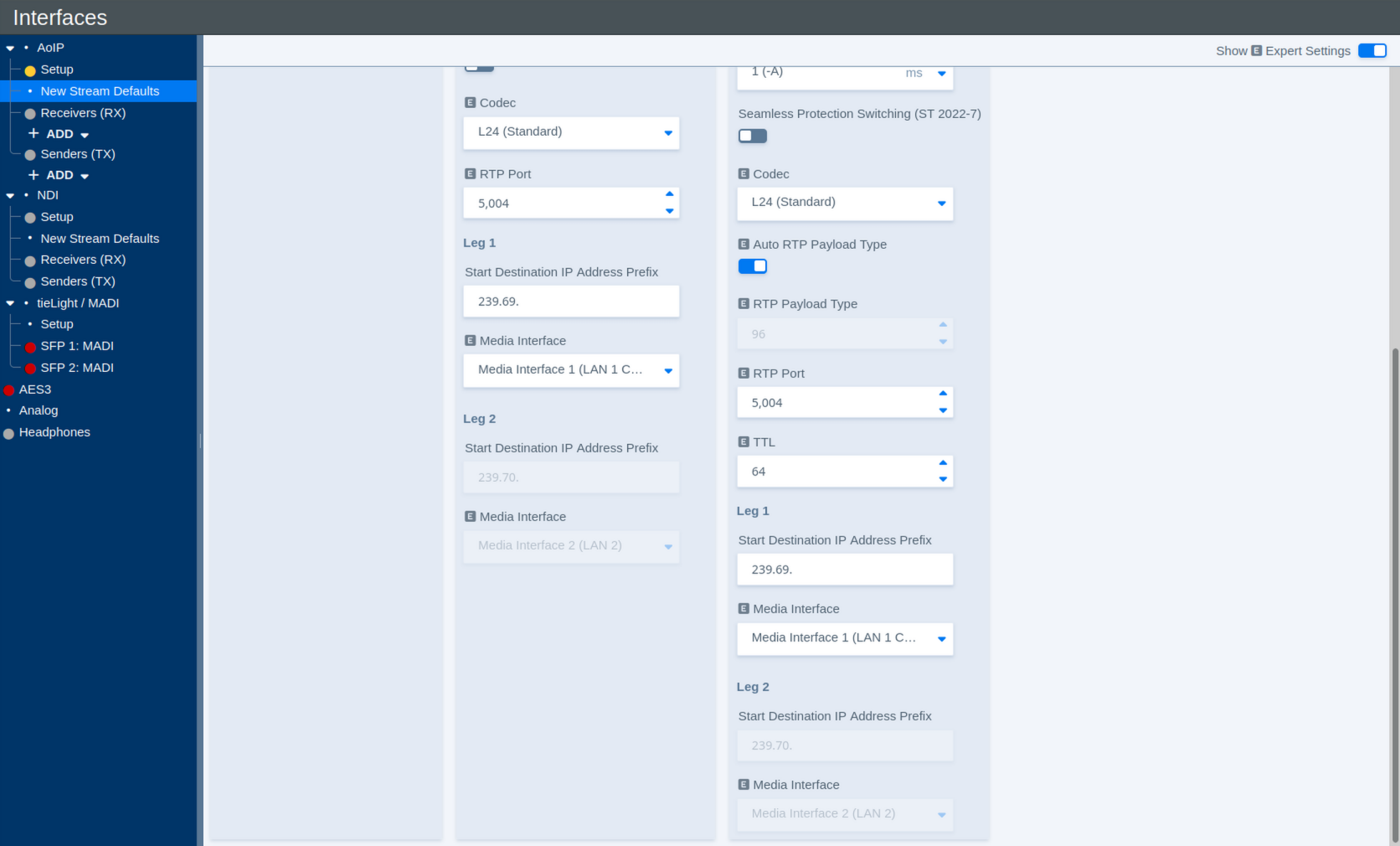
The Expert View adds further Receiver and Sender defaults.
Receiver – Additional Settings
| Parameter | Values | Default | Description |
|---|---|---|---|
| Codec | Available codecs | - | Defines the default audio codec or sample format used for newly created receivers. |
| RTP Port | Port number | - | Defines the RTP port used for newly created receiver streams. |
| Media Interface – Leg 1 | Available Media Interfaces | - | Selects the Media Interface used for the first stream leg. |
| Media Interface – Leg 2 | Available Media Interfaces | - | Selects the Media Interface used for the redundant second stream leg when ST 2022-7 is enabled. |
Sender – Additional Settings
| Parameter | Values | Default | Description |
|---|---|---|---|
| Codec | Available codecs | - | Defines the audio codec or sample format used for newly created sender streams. |
| Auto RTP Payload Type | On / Off | - | Automatically assigns a suitable RTP payload type to newly created streams. Disable this option to specify the payload type manually. |
| RTP Payload Type | RTP payload type | - | Defines the RTP payload type when automatic assignment is disabled. |
| RTP Port | Port number | - | Defines the RTP port used for newly created sender streams. |
| TTL | Number of network hops | - | Defines the IP multicast Time To Live (TTL). The value limits how many routed network hops a multicast stream can traverse. |
| Media Interface – Leg 1 | Available Media Interfaces | - | Selects the Media Interface used to transmit the first stream leg. |
| Media Interface – Leg 2 | Available Media Interfaces | - | Selects the Media Interface used to transmit the redundant second stream leg when ST 2022-7 is enabled. |
Livewire
When Livewire is selected under Protocol Selection, some of the New Stream Defaults differ from those available for ST 2110.
Instead of assigning multicast destination addresses directly, Livewire uses Livewire Channel numbers. These channel numbers determine the corresponding multicast destination used by the Livewire stream.
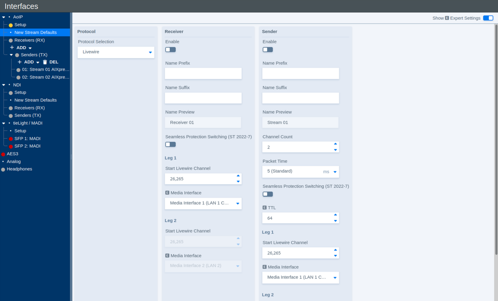
Receiver Defaults
| Parameter | Values | Default | Description |
|---|---|---|---|
| Enable | On / Off | - | Defines whether newly created Livewire receivers are enabled by default. |
| Name Prefix | Text | - | Defines an optional prefix added to the name of newly created receivers. |
| Name Suffix | Text | - | Defines an optional suffix added to the name of newly created receivers. |
| Name Preview | Status | - | Shows a preview of the resulting receiver name. |
| Seamless Protection Switching (ST 2022-7) | On / Off | - | Enables SMPTE ST 2022-7 seamless protection switching for newly created receivers. |
| Start Livewire Channel – Leg 1 | Livewire channel number | - | Defines the first Livewire Channel number used for automatically created receiver streams. When multiple streams are created, the channel number is incremented automatically. |
| Media Interface – Leg 1 | Available Media Interfaces | - | Selects the Media Interface used for the first stream leg. |
| Start Livewire Channel – Leg 2 | Livewire channel number | - | Defines the starting Livewire Channel number for the redundant second stream leg. When multiple streams are created, the channel number is incremented automatically. |
| Media Interface – Leg 2 | Available Media Interfaces | - | Selects the Media Interface used for the redundant second stream leg when ST 2022-7 is enabled. |
Sender Defaults
| Parameter | Values | Default | Description |
|---|---|---|---|
| Enable | On / Off | - | Defines whether newly created Livewire senders are enabled by default. |
| Name Prefix | Text | - | Defines an optional prefix added to the name of newly created senders. |
| Name Suffix | Text | - | Defines an optional suffix added to the name of newly created senders. |
| Name Preview | Status | - | Shows a preview of the resulting sender name. |
| Channel Count | Supported channel counts | - | Defines the default number of audio channels for a newly created Livewire sender. |
| Packet Time | Supported packet times | - | Defines the packet time used for newly created Livewire streams. Shorter packet times reduce transport latency but increase the packet rate and processing load. |
| Seamless Protection Switching (ST 2022-7) | On / Off | - | Enables SMPTE ST 2022-7 seamless protection switching for newly created senders. |
| TTL | Number of network hops | - | Defines the IP multicast Time To Live (TTL). The value limits how many routed network hops a multicast stream can traverse. |
| Start Livewire Channel – Leg 1 | Livewire channel number | - | Defines the first Livewire Channel number used for automatically created sender streams. When multiple streams are created, the channel number is incremented automatically. |
| Media Interface – Leg 1 | Available Media Interfaces | - | Selects the Media Interface used to transmit the first stream leg. |
| Start Livewire Channel – Leg 2 | Livewire channel number | - | Defines the starting Livewire Channel number for the redundant second stream leg. When multiple streams are created, the channel number is incremented automatically. |
| Media Interface – Leg 2 | Available Media Interfaces | - | Selects the Media Interface used to transmit the redundant second stream leg when ST 2022-7 is enabled. |
Audio over IP - Receivers
Receivers
The Receivers (RX) section under AoIP contains the receive streams configured on the flexAI system.
Use ADD to create a new receiver. Existing receivers are listed below Receivers (RX) and can be selected individually for configuration. Use DEL to remove selected receivers.
Some receiver parameters are only visible when Show Expert Settings is enabled.
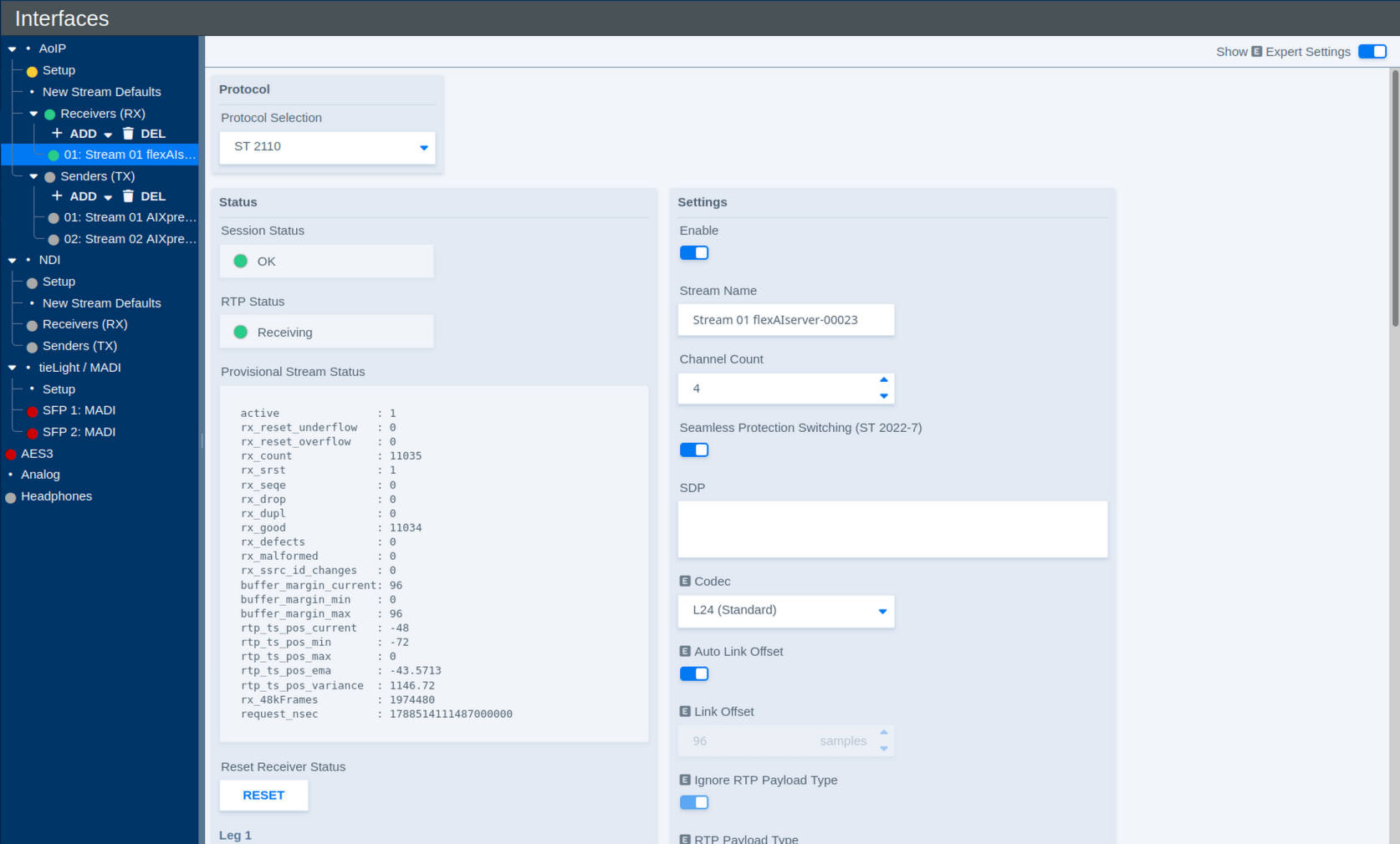
Protocol
| Parameter | Values | Default | Description |
|---|---|---|---|
| Protocol Selection | Available AoIP protocols | - | Selects the protocol used by the receiver. The available settings may change depending on the selected protocol. |
Status
The Status section shows the current operating state of the receiver and its stream legs.
| Parameter | Values | Default | Description |
|---|---|---|---|
| Session Status | Status | - | Shows the overall status of the receive session. |
| RTP Status | Status | - | Shows whether RTP packets are currently being received. |
| Provisional Stream Status | Diagnostic information | - | Provides detailed receiver statistics and diagnostic information about the incoming RTP stream. |
| Reset Receiver Status | Button | - | Resets the displayed receiver status and diagnostic counters. |
| RTP Status – Leg 1 | Status | - | Shows the receive status of both stream legs combined. |
| RTP Status – Leg 2 | Status | - | Currently not used |
The Provisional Stream Status is primarily intended for diagnostics and troubleshooting. For normal operation, the Session and RTP status indicators provide the most relevant overview.
Settings
| Parameter | Values | Default | Description |
|---|---|---|---|
| Enable | On / Off | - | Enables or disables the receiver. |
| Stream Name | Text | - | Defines the name used to identify the receiver within the flexAI system. |
| Channel Count | Supported channel counts | - | Defines the number of audio channels carried by the receive stream. |
| Seamless Protection Switching (ST 2022-7) | On / Off | - | Enables SMPTE ST 2022-7 seamless protection switching. When enabled, two redundant stream legs can be received over separate network paths. |
| SDP | SDP data | - | Defines the Session Description Protocol information for the incoming stream. The original SDP provided by the sender can be pasted directly into this field. Alternatively, SDP information can be obtained from a discovered stream. |
| Codec | Available codecs | - | Defines the expected audio codec or sample format of the incoming stream. |
| Auto Link Offset | On / Off | - | Automatically applies the Link Offset configured for the corresponding stream type and packet time on the AoIP Setup page. |
| Link Offset | Delay in samples | - | Defines the fixed receive/playout delay when Auto Link Offset is disabled. The delay remains constant for the stream, providing deterministic latency. |
| Ignore RTP Payload Type | On / Off | - | Defines whether the configured RTP Payload Type is ignored when receiving the stream. |
| RTP Payload Type | RTP payload type | - | Defines the expected RTP payload type when payload-type checking is used. |
| RTP Port | Port number | - | Defines the UDP port on which the RTP stream is received. |
Pasting the sender's original SDP is often the simplest way to configure a receiver manually, as it transfers the relevant stream parameters in a single step.
Stream Legs
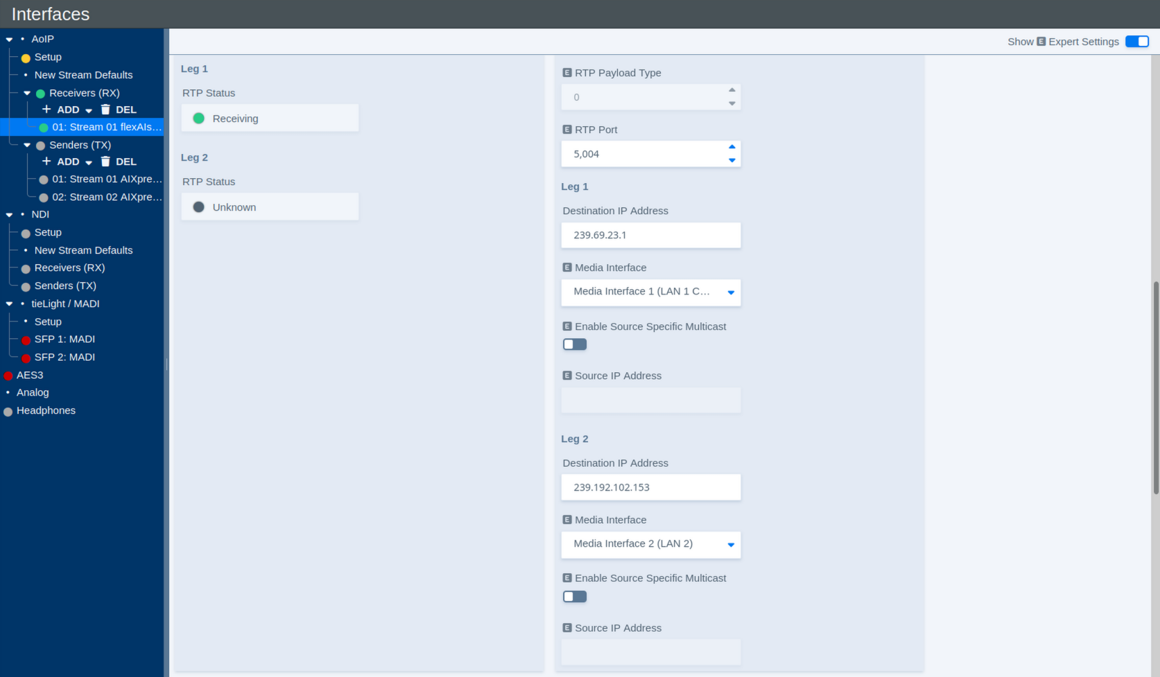
Each receiver can use up to two stream legs. Leg 1 carries the primary stream. Leg 2 is used for redundant reception when ST 2022-7 is enabled.
The following parameters are available for each leg:
| Parameter | Values | Default | Description |
|---|---|---|---|
| Destination IP Address | Multicast IP address | - | Defines the multicast destination address from which the receiver joins the stream. |
| Media Interface | Available Media Interfaces | - | Selects the Media Interface used to receive this stream leg. |
| Enable Source Specific Multicast | On / Off | - | Enables Source-Specific Multicast (SSM) for this stream leg. |
| Source IP Address | IP address | - | Defines the expected source address when Source-Specific Multicast is enabled. |
Each receiver can be assigned individually to one of the available Media Interfaces. This allows different receivers, and, with ST 2022-7, individual stream legs, to use separate physical AoIP networks.
In combination with the internal audio routing, flexAI can also transfer audio between otherwise independent AoIP networks: audio received through one Media Interface can be routed internally and transmitted again through a sender assigned to another Media Interface. This operates at the audio level rather than as a network bridge.
With Source-Specific Multicast (SSM) enabled, the receiver joins the multicast stream from the specified source address rather than accepting traffic for the multicast group from any source.
Stream Discovery
The Discovery section can be used to find available AoIP streams on the network and apply their parameters to the selected receiver.
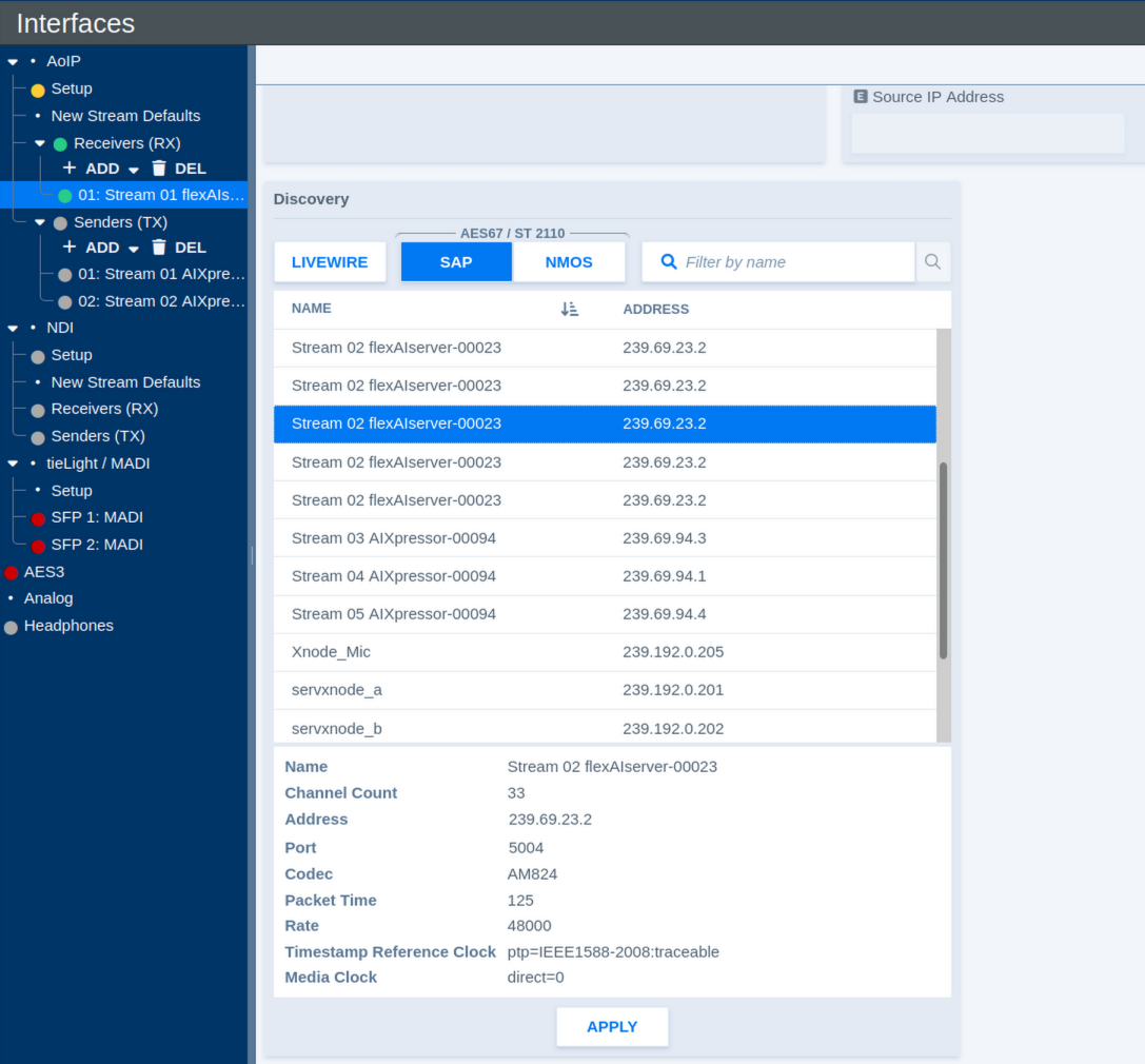
Available discovery methods include:
- Livewire
- SAP for AES67 / ST 2110
- NMOS
Use the protocol buttons to select the desired discovery method. The Filter by name field can be used to narrow the list of discovered streams.
Select a stream to display the information advertised by the sender. Depending on the protocol, this may include information such as:
- Name
- Channel Count
- Destination Address
- RTP Port
- Codec
- Packet Time
- Sample Rate
- Timestamp Reference Clock
- Media Clock
Click Apply to connect the selected stream with the current receiver.
This provides a convenient alternative to entering the receiver parameters manually and helps ensure that the receiver settings match those advertised by the sender.
Livewire Receiver Settings
When Livewire is selected under Protocol Selection, some receiver parameters differ from those used for ST 2110.
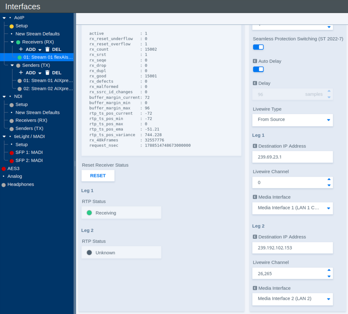
| Parameter | Values | Default | Description |
|---|---|---|---|
| Auto Delay | On / Off | - | Automatically applies the receive delay configured for the corresponding Livewire stream type on the AoIP Setup page. |
| Delay | Delay in samples | - | Defines the fixed receive/playout delay when Auto Delay is disabled. The configured delay remains constant, providing deterministic latency. |
| Livewire Type | Available Livewire types | - | Defines how the Livewire stream is addressed. To Source uses the Livewire channel information associated with the source stream. |
| Destination IP Address – Leg 1 | Multicast IP address | - | Shows or defines the multicast destination address used for the first Livewire stream leg. |
| Livewire Channel – Leg 1 | Livewire channel number | - | Defines the Livewire Channel used for the first stream leg. The Livewire Channel identifies the corresponding stream within the Livewire network. |
| Media Interface – Leg 1 | Available Media Interfaces | - | Selects the Media Interface used to receive the first stream leg. |
| Destination IP Address – Leg 2 | Multicast IP address | - | Shows or defines the multicast destination address used for the redundant second stream leg. |
| Livewire Channel – Leg 2 | Livewire channel number | - | Defines the Livewire Channel used for the redundant second stream leg. |
| Media Interface – Leg 2 | Available Media Interfaces | - | Selects the Media Interface used to receive the redundant second stream leg when ST 2022-7 is enabled. |
As with other receiver types, Leg 2 is used for redundant reception when Seamless Protection Switching (ST 2022-7) is enabled.
Audio over IP - Senders
Senders
The Senders (TX) section under AoIP contains the transmit streams configured on the flexAI system.
Use ADD to create a new sender. Existing senders are listed below Senders (TX) and can be selected individually for configuration. Use DEL to remove selected senders.
Some sender parameters are only visible when Show Expert Settings is enabled.
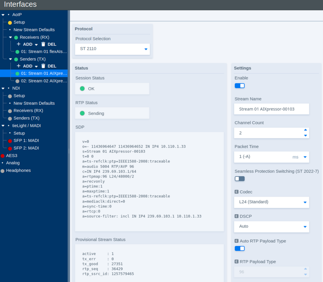
Protocol
| Parameter | Values | Default | Description |
|---|---|---|---|
| Protocol Selection | Available AoIP protocols | - | Selects the protocol used by the sender. The available settings may change depending on the selected protocol. |
Status
The Status section shows the current operating state of the sender and provides the SDP describing the transmitted stream.
| Parameter | Values | Default | Description |
|---|---|---|---|
| Session Status | Status | - | Shows the overall status of the transmit session. |
| RTP Status | Status | - | Shows whether RTP packets are currently being transmitted. |
| SDP | Status / SDP data | - | Shows the Session Description Protocol data generated for the transmitted stream. This information can be used to configure compatible receivers. |
| Provisional Stream Status | Diagnostic information | - | Provides detailed sender statistics and diagnostic information about the outgoing RTP stream. |
| Reset Sender Status | Button | - | Resets the displayed sender status and diagnostic counters. |
| RTP Status – Leg 1 | Status | - | Shows the transmit status of the first stream leg. |
| RTP Status – Leg 2 | Status | - | Shows the transmit status of the redundant second stream leg when ST 2022-7 is used. |
To copy the complete SDP, move the pointer over the displayed SDP. A copy control appears; click it to copy the SDP to the clipboard. The copied SDP can then be pasted directly into a compatible receiver or another application.
The Provisional Stream Status is primarily intended for diagnostics and troubleshooting. For normal operation, the Session and RTP status indicators provide the most relevant overview.
Settings
The Settings section defines the format and network properties of the transmitted stream.
| Parameter | Values | Default | Description |
|---|---|---|---|
| Enable | On / Off | - | Enables or disables the sender. |
| Stream Name | Text | - | Defines the name used to identify and advertise the transmitted stream. |
| Channel Count | Supported channel counts | - | Defines the number of audio channels carried by the stream. |
| Packet Time | Supported packet times | - | Defines the duration of audio carried by each RTP packet. Shorter packet times reduce transport latency but increase the packet rate and processing load. |
| Seamless Protection Switching (ST 2022-7) | On / Off | - | Enables SMPTE ST 2022-7 seamless protection switching. When enabled, two equivalent stream legs are transmitted over separate network paths. |
| Codec | Available codecs | - | Defines the audio codec or sample format used for the transmitted stream. |
| DSCP | Auto / Available DSCP values | - | Defines the Differentiated Services Code Point used to classify the outgoing RTP traffic for Quality of Service (QoS). Auto applies the DSCP value configured for the corresponding stream type and packet time on the AoIP Setup page. |
| Auto RTP Payload Type | On / Off | - | Automatically assigns the RTP payload type. Disable this option to specify the payload type manually. |
| RTP Payload Type | RTP payload type | - | Defines the RTP payload type when automatic assignment is disabled. |
| RTP Port | Port number | - | Defines the UDP destination port used for the RTP stream. |
| TTL | Number of network hops | - | Defines the IP multicast Time To Live (TTL), limiting how many routed network hops the multicast stream can traverse. |
DSCP (Differentiated Services Code Point) allows network infrastructure to classify AoIP traffic for Quality of Service. Switches and routers can use this marking to give time-critical audio traffic the required priority over less critical network traffic.
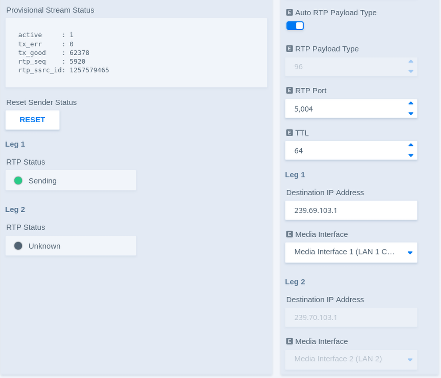
Stream Legs
Each sender can use up to two stream legs. Leg 1 carries the primary stream. Leg 2 carries an equivalent redundant stream when ST 2022-7 is enabled.
| Parameter | Values | Default | Description |
|---|---|---|---|
| Destination IP Address – Leg 1 | Multicast IP address | - | Defines the multicast destination address used to transmit the first stream leg. |
| Media Interface – Leg 1 | Available Media Interfaces | - | Selects the Media Interface used to transmit the first stream leg. |
| Destination IP Address – Leg 2 | Multicast IP address | - | Defines the multicast destination address used to transmit the redundant second stream leg. |
| Media Interface – Leg 2 | Available Media Interfaces | - | Selects the Media Interface used to transmit the redundant second stream leg when ST 2022-7 is enabled. |
Each sender can be assigned individually to one of the available Media Interfaces. This allows different senders, and, with ST 2022-7, individual stream legs, to use separate physical AoIP networks.
In combination with the internal audio routing, flexAI can also transfer audio between otherwise independent AoIP networks: audio received through one Media Interface can be routed internally and transmitted again through a sender assigned to another Media Interface. This operates at the audio level rather than as a network bridge.
With ST 2022-7 enabled, both legs carry equivalent audio data over independent network paths. A compatible receiver can use both legs for seamless protection against packet loss or a failure of one network path.
Livewire Sender Settings
When Livewire is selected under Protocol Selection, some sender parameters differ from those used for ST 2110.
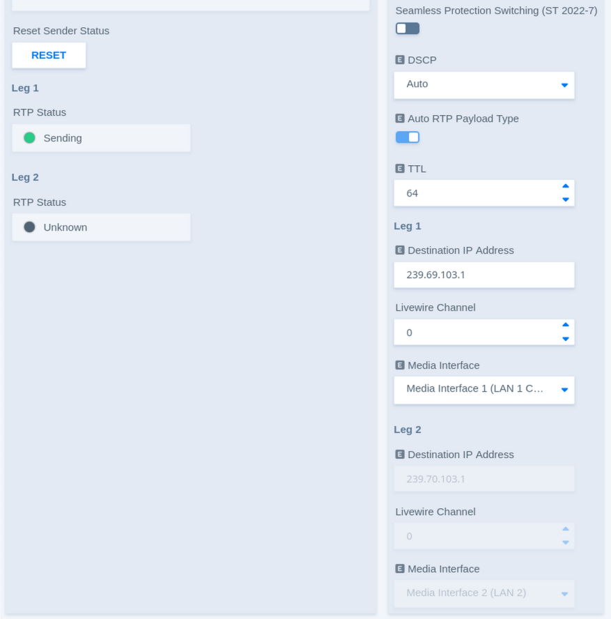
The general sender controls, status information, packet time, DSCP, and redundancy settings operate in the same way as described above. Livewire additionally uses a Livewire Channel to identify the transmitted stream.
| Parameter | Values | Default | Description |
|---|---|---|---|
| Destination IP Address – Leg 1 | Multicast IP address | - | Shows or defines the multicast destination address used for the first Livewire stream leg. |
| Livewire Channel – Leg 1 | Livewire channel number | - | Defines the Livewire Channel used for the first stream leg. The channel number identifies the stream within the Livewire network and corresponds to its multicast destination. |
| Media Interface – Leg 1 | Available Media Interfaces | - | Selects the Media Interface used to transmit the first Livewire stream leg. |
| Destination IP Address – Leg 2 | Multicast IP address | - | Shows or defines the multicast destination address used for the redundant second Livewire stream leg. |
| Livewire Channel – Leg 2 | Livewire channel number | - | Defines the Livewire Channel used for the redundant second stream leg. |
| Media Interface – Leg 2 | Available Media Interfaces | - | Selects the Media Interface used to transmit the redundant second stream leg when ST 2022-7 is enabled. |
As with other sender types, Leg 2 is used when Seamless Protection Switching (ST 2022-7) is enabled.
tieLight / MADI
MADI / tieLight
The tieLight / MADI section configures the SFP-based multichannel audio interfaces available on compatible flexAI systems.
The two SFP interfaces can be operated independently, as a redundant pair, or individually assigned to MADI and tieLight.
MADI and tieLight require different SFP module types and are not interchangeable. When changing an interface between MADI and tieLight, make sure that the appropriate SFP module is installed.
tieLight is a proprietary Jünger Audio point-to-point interface for transporting multichannel audio between compatible systems. It remains supported on compatible hardware but requires additional configuration.
Setup
Select Setup under tieLight / MADI to configure the operating mode of the two interfaces.
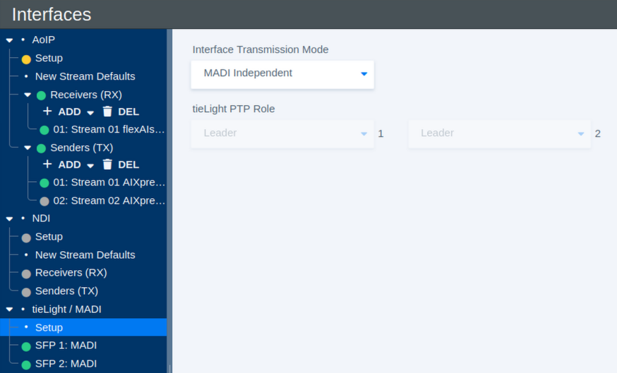
| Parameter | Values | Default | Description |
|---|---|---|---|
| Interface Transmission Mode | MADI Independent / MADI Redundant / tieLight Independent / tieLight Redundant / IF1:MADI IF2:tieLight / IF1:tieLight IF2:MADI | - | Defines how the two SFP interfaces are used and whether they operate independently or as a redundant pair. |
| tieLight PTP Role – Interface 1 | Available PTP roles | - | Defines the PTP role of Interface 1 when it is configured for tieLight. |
| tieLight PTP Role – Interface 2 | Available PTP roles | - | Defines the PTP role of Interface 2 when it is configured for tieLight. |
Interface Transmission Modes
MADI Independent operates both interfaces as separate MADI interfaces. Each interface can carry its own audio signals.
MADI Redundant operates the two interfaces as a redundant MADI pair. Both interfaces carry the same channels, providing an alternative path if one connection fails.
tieLight Independent operates both interfaces as separate tieLight connections.
tieLight Redundant operates the two interfaces as a redundant tieLight pair.
The mixed modes IF1:MADI IF2:tieLight and IF1:tieLight IF2:MADI allow one SFP interface to carry MADI while the other carries tieLight.
When selecting a different transmission mode, also check that the SFP module installed in each interface matches the selected protocol.
The redundancy function monitors the availability of the complete MADI or tieLight signal path. It can switch to the redundant interface if the primary signal is lost, but it does not detect or compensate for failures affecting individual audio channels within an otherwise valid signal.
MADI Interface Status
Select an individual MADI interface, such as SFP 1: MADI or SFP 2: MADI, to view its current receive and signal status.
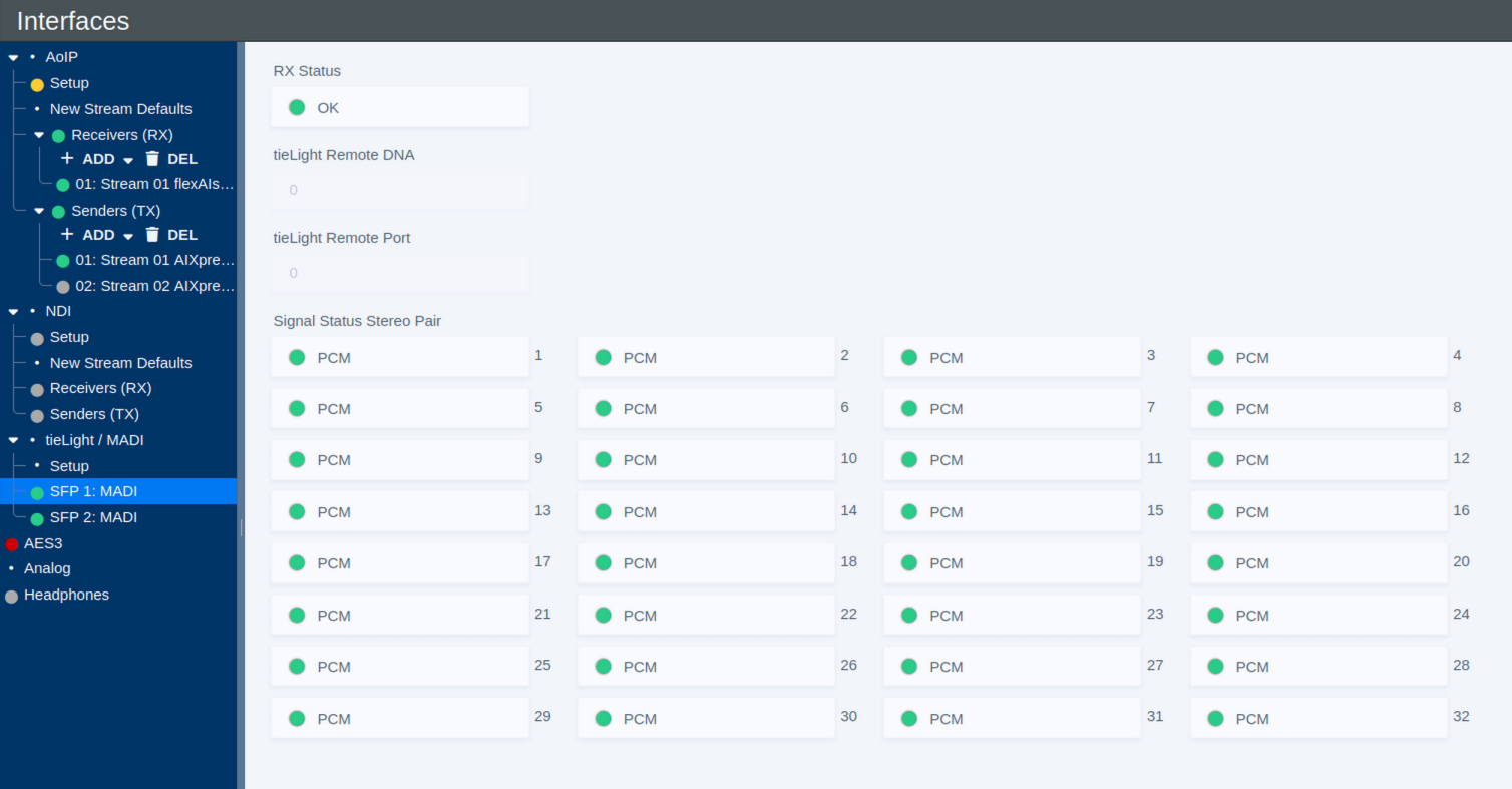
| Parameter | Values | Default | Description |
|---|---|---|---|
| RX Status | Status | - | Shows the overall receive status of the MADI interface. |
| Signal Status Stereo Pair | Status per stereo pair | - | Shows the detected signal status for each of the 32 stereo pairs carried by the 64-channel MADI interface. A status such as PCM indicates that PCM audio is detected for the corresponding pair. |
The per-pair status display provides a quick overview of the incoming MADI signal and can be useful when checking the connection and available audio channels.
tieLight Status
When an SFP interface is operated in tieLight mode, the interface page provides status information for the tieLight connection, including information about the connected remote endpoint.
| Parameter | Values | Default | Description |
|---|---|---|---|
| RX Status | Status | - | Shows the overall receive status of the tieLight interface. |
| tieLight Remote DNA | Status | - | Shows the DNA identifier reported by the remote tieLight device. |
| tieLight Remote Port | Status | - | Shows the remote tieLight port associated with the connection. |
AES3
The AES3 page provides configuration and status information for the system's AES3 inputs and outputs. AES3, also commonly referred to as AES/EBU, is a professional digital audio interface standard for transmitting two channels of audio together with related channel status information.
The interface is organized in stereo pairs. Depending on the selected I/O mode, the available AES3 connections are configured either as 8 Inputs / 8 Outputs or 4 Inputs / 12 Outputs.
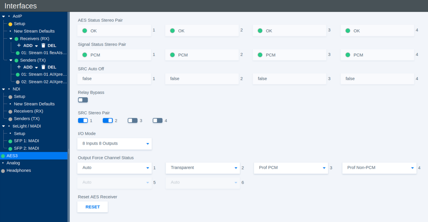
Input Status
The input status indicators provide information about the AES3 signal detected on each stereo pair.
| Parameter | Values | Default | Description |
|---|---|---|---|
| AES Status Stereo Pair | Status | - | Shows whether a valid AES3 signal is detected for each input stereo pair. |
| Signal Status Stereo Pair | Status | - | Shows the detected signal type for each stereo pair, for example **PCM**. |
| SRC Auto Off | Status | - | Shows whether the Sample Rate Converter (SRC) has been automatically disabled for the corresponding stereo pair. |
Sample Rate Conversion
Sample Rate Conversion can be enabled individually for each AES3 input stereo pair.
| Parameter | Values | Default | Description |
|---|---|---|---|
| SRC Stereo Pair 1–4 | On / Off | - | Enables or disables Sample Rate Conversion for the corresponding AES3 input stereo pair. SRC allows incoming AES3 signals with a different or asynchronous sample rate to be converted to the system sample rate. |
Relay Bypass
| Parameter | Values | Default | Description |
|---|---|---|---|
| Relay Bypass | On / Off | - | Activates the AES3 relay bypass path, allowing the corresponding AES3 signal path to bypass normal processing where supported by the hardware. |
I/O Mode
The available AES3 connections can be distributed between inputs and outputs in two ways.
| Parameter | Values | Default | Description |
|---|---|---|---|
| I/O Mode | 8 Inputs 8 Outputs / 4 Inputs 12 Outputs | - | Selects how the available AES3 interfaces are allocated between inputs and outputs. |
Output Channel Status
AES3 carries additional Channel Status information alongside the audio data. The Output Force Channel Status settings define how this information is generated for each AES3 output stereo pair.
| Parameter | Values | Default | Description |
|---|---|---|---|
| Output Force Channel Status | Auto / Transparent / Prof PCM / Prof Non-PCM / Consumer PCM / Consumer Non-PCM | - | Defines the AES3 Channel Status information transmitted with the corresponding output stereo pair. |
The available modes are:
| Mode | Description |
|---|---|
| Auto | Automatically generates channel status information appropriate for the transmitted signal. |
| Transparent | Passes the available incoming channel status information through to the output without intentionally changing its format. |
| Prof PCM | Forces professional AES3 channel status and identifies the signal as linear PCM audio. |
| Prof Non-PCM | Forces professional AES3 channel status and identifies the signal as non-PCM data. |
| Consumer PCM | Forces consumer-format channel status and identifies the signal as linear PCM audio. |
| Consumer Non-PCM | Forces consumer-format channel status and identifies the signal as non-PCM data. |
The Non-PCM modes are intended for signals carrying encoded or other non-linear audio data rather than conventional PCM samples.
Reset AES Receiver
In case an AES3 receiver does not lock correctly to an incoming signal, the corresponding receiver status may remain red.
| Parameter | Values | Default | Description |
|---|---|---|---|
| Reset AES Receiver | Button | - | Resets the AES3 receiver state. If an input does not lock correctly and its status remains red, click Reset to re-establish synchronization with the incoming signal. |
Depending on the hardware platform, the Reset AES Receiver button may not be available. On these systems, receiver recovery is monitored and handled automatically.
Analog
The Analog page provides status information and I/O configuration for the system's analog audio interfaces.
The available number of analog inputs and outputs depends on the selected I/O mode.
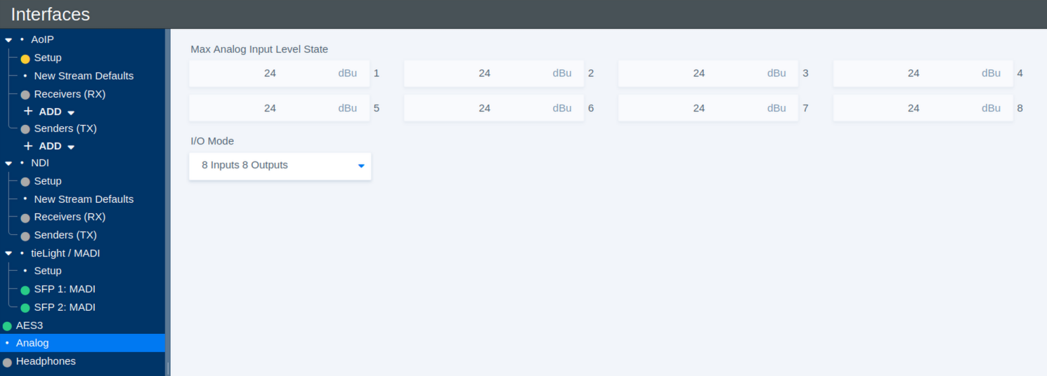
Maximum Analog Input Level
The Max Analog Input Level State shows the analog input level that corresponds to 0 dBFS for each input channel.
| Parameter | Values | Default | Description |
|---|---|---|---|
| Max Analog Input Level State | Hardware-dependent, typically +24 dBu or +18 dBu | - | Shows the maximum analog input level corresponding to 0 dBFS for each channel. The value is read from the installed hardware and cannot be changed from the user interface. |
On some hardware variants, the maximum input level can be changed physically by repositioning a jumper on the interface hardware. Depending on the jumper setting, the maximum input level is typically +24 dBu or +18 dBu. The value shown on this page reflects the current hardware configuration.
I/O Mode
| Parameter | Values | Default | Description |
|---|---|---|---|
| I/O Mode | 8 Inputs 8 Outputs / 4 Inputs 12 Outputs | - | Selects how the available analog audio channels are distributed between inputs and outputs. |
Headphone
The Headphones page provides level control for the system's headphone output.
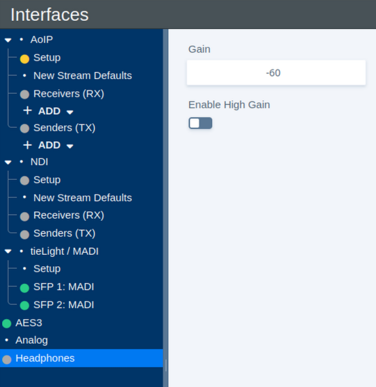
Headphone Level
| Parameter | Values | Default | Description |
|---|---|---|---|
| Gain | -80 dBFS to -18 dBFS; up to 0 dBFS with High Gain enabled | - | Sets the headphone output level. With High Gain disabled, the available range is -80 dBFS to -18 dBFS. |
| Enable High Gain | On / Off | - | Extends the available gain range up to 0 dBFS. |
NDI
Dante
Sync
Sync
The Sync page defines the synchronization sources and clock settings used by the flexAI system. It also shows the currently active synchronization source and the status of the available sync inputs.
The exact synchronization sources available on this page depend on the installed interfaces and the system configuration.
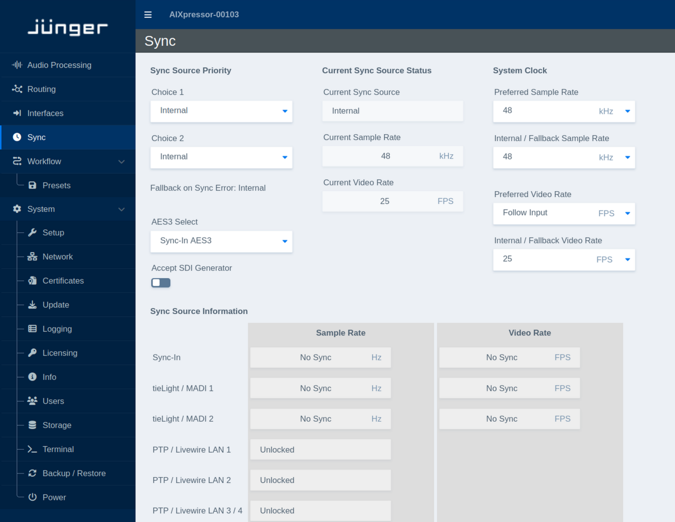
Sync Source Priority
This section defines which synchronization sources the system should use and in which order.
| Parameter | Values | Default | Description |
|---|---|---|---|
| Choice 1 | Available sync sources | - | Defines the preferred synchronization source. The system uses this source whenever a valid sync signal is available. |
| Choice 2 | Available sync sources | - | Defines the secondary synchronization source. It is used if the source selected as Choice 1 is not available or not valid. |
| Fallback on Sync Error | Status | - | Shows the synchronization source used if none of the configured external sync sources can provide a valid signal. The internal clock is used as the final fallback. |
| AES3 Select | Available AES3 sync inputs | - | Selects the AES3 input to be used when AES3 synchronization is selected. The available inputs depend on the installed hardware and interfaces. |
| Accept SDI Generator | On / Off | - | Defines whether synchronization provided by an SDI generator is accepted as a valid sync source. |
Current Sync Source Status
This section shows the synchronization currently used by the system.
| Parameter | Values | Default | Description |
|---|---|---|---|
| Current Sync Source | Status | - | Shows the synchronization source currently used by the flexAI system. |
| Current Sample Rate | Status | - | Shows the current audio sample rate of the system in kHz. |
| Current Video Rate | Status | - | Shows the current video frame rate in FPS. |
System Clock
This section defines the preferred audio and video clock parameters and the values used when the system operates from its internal clock.
| Parameter | Values | Default | Description |
|---|---|---|---|
| Preferred Sample Rate | Supported sample rates | - | Defines the preferred audio sample rate when the selected synchronization source supports or requires a sample-rate selection. |
| Internal / Fallback Sample Rate | Supported sample rates | - | Defines the sample rate used when the system is running from its internal clock or has fallen back to internal synchronization. |
| Preferred Video Rate | Supported video rates / Follow Input | - | Defines the preferred video frame rate. Select Follow Input to follow the video rate provided by the active synchronization source. |
| Internal / Fallback Video Rate | Supported video rates | - | Defines the video frame rate used when the system is running from its internal clock or has fallen back to internal synchronization. |
Sync Source Information
The Sync Source Information section provides a live overview of the synchronization signals detected on the available inputs.
For each sync-capable interface, the table shows the detected Sample Rate and, where applicable, the Video Rate. Depending on the interface and signal state, entries may display a detected rate or a status such as No Sync or Unlocked.
This overview can be used to verify which synchronization signals are currently available before selecting them as a preferred sync source.
Workflow
Presets
The Presets page under Workflow provides an overview of the presets stored on the flexAI system and allows them to be imported, exported, and deleted.
The preset list shows the Name, optional Description, Type, and Sub-Type of each preset. This makes it easier to identify which part of the system or processing function a preset belongs to.
Click Export All Presets to export the complete preset collection.
Use Import Presets to import presets from a previously exported preset file.
Individual presets can also be exported using the export button at the right-hand side of the corresponding entry.
To remove presets, select one or more entries using the checkboxes and click Delete Selected Presets.
System
Setup
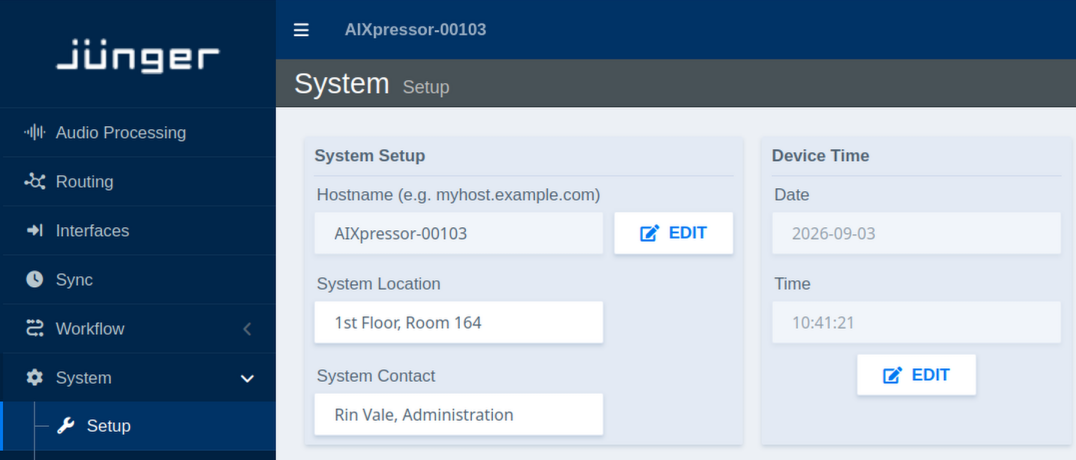
System Setup:
| Parameter | Values | Default | Description |
|---|---|---|---|
| Hostname | Text | Device name | Sets the network hostname for device identification (click Edit) |
| System Location | Text | - | Defines the physical location of the device for administrative purposes |
| System Contact | Text | - | Specifies contact person or department responsible for the device |
Device Time:
| Parameter | Values | Default | Description |
|---|---|---|---|
| Current Date | Status | - | Displays the current device date |
| Current Time | Status | - | Displays the current device time |
| Edit | Button | - | Opens time configuration dialog. |
Note: Manually set values may be overridden by NTP synchronization (see System → Network → NTP)
Network
This section describes the network-related settings available in the flexAI web interface.
The examples in this section use **LAN 1 CTRL**, as labeled on the AIXpressor. The same configuration options are available for the other network interfaces, depending on the physical configuration of the flexAI system.
Important - IGMP Snooping must be enabled on all switch ports connected to flexAI systems. Otherwise, forwarded multicast traffic may stress the connected system.
Overview
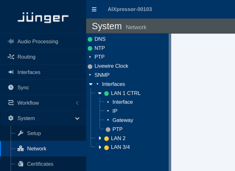
DNS
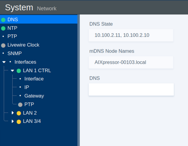
The DNS section provides the name resolution and local network discovery settings.
| Parameter | Values | Default | Description |
|---|---|---|---|
| DNS State | Status | - | Shows the current DNS state. |
| mDNS Node Name | Status | - | Shows the multicast DNS (mDNS) name used for local network discovery. |
| DNS | On / Off | - | Enables or disables standard DNS resolution for domain name lookups. |
NTP
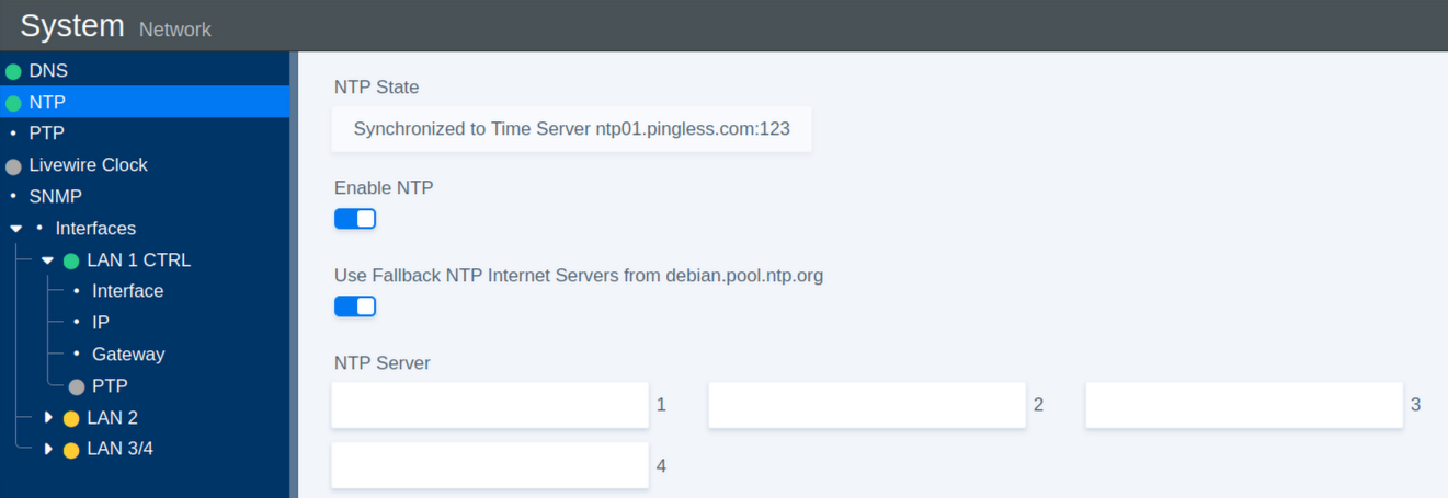
The NTP section configures Network Time Protocol synchronization for the system clock.
| Parameter | Values | Default | Description |
|---|---|---|---|
| NTP State | Status | - | Shows the NTP server to which the system is currently synchronized. |
| Enable NTP | On / Off | On | Enables or disables NTP time synchronization. |
| Use Fallback | On / Off | On | Enables fallback to public Debian NTP servers if none of the configured servers are available. |
| NTP Server 1 | URL | - | Defines the primary NTP server. |
| NTP Server 2 | URL | - | Defines the secondary NTP server. |
| NTP Server 3 | URL | - | Defines the tertiary NTP server. |
| NTP Server 4 | URL | - | Defines the fourth NTP server. |
Livewire Clock
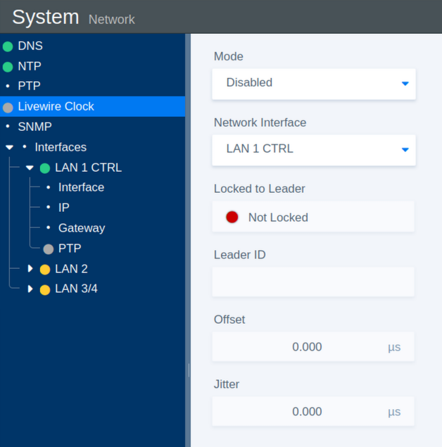
The Livewire Clock section provides synchronization settings and status information for Livewire clocking.
| Parameter | Values | Default | Description |
|---|---|---|---|
| Mode | On / Off | On | Enables or disables Livewire clock synchronization. |
| Network Interface | Select | - | Selects the network interface used for Livewire clock communication. |
| Locked to Leader | Status | - | Indicates whether the system is synchronized to the current Leader Clock. |
| Leader ID | Status | - | Shows the identifier of the current Leader Clock. |
| Offset | Status | - | Shows the time offset between the system and the Leader Clock. |
| Jitter | Status | - | Shows the measured timing jitter. |
SNMP
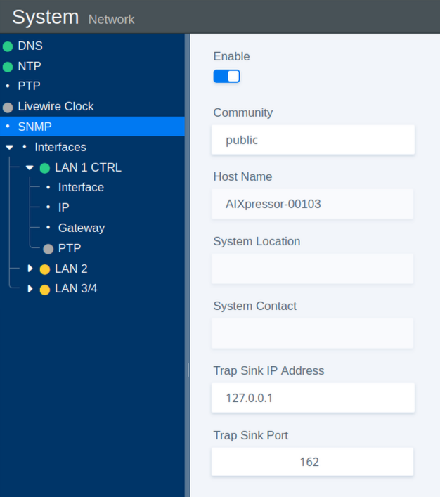
The SNMP section configures Simple Network Management Protocol monitoring.
| Parameter | Values | Default | Description |
|---|---|---|---|
| Enable | On / Off | On | Enables or disables the SNMP agent. |
| Community | Name | public | Defines the community string used for SNMP access. |
| Host Name | Status | - | Shows the system host name. |
| System Location | Status | - | Shows the configured physical location of the system. |
| System Contact | Status | - | Shows the configured contact information for the system. |
| Trap Sink IP Address | IP Address | - | Defines the destination IP address for SNMP trap messages. |
| Trap Sink Port | Port Number | 162 | Defines the destination port for SNMP trap messages. |
Interfaces: IP Address
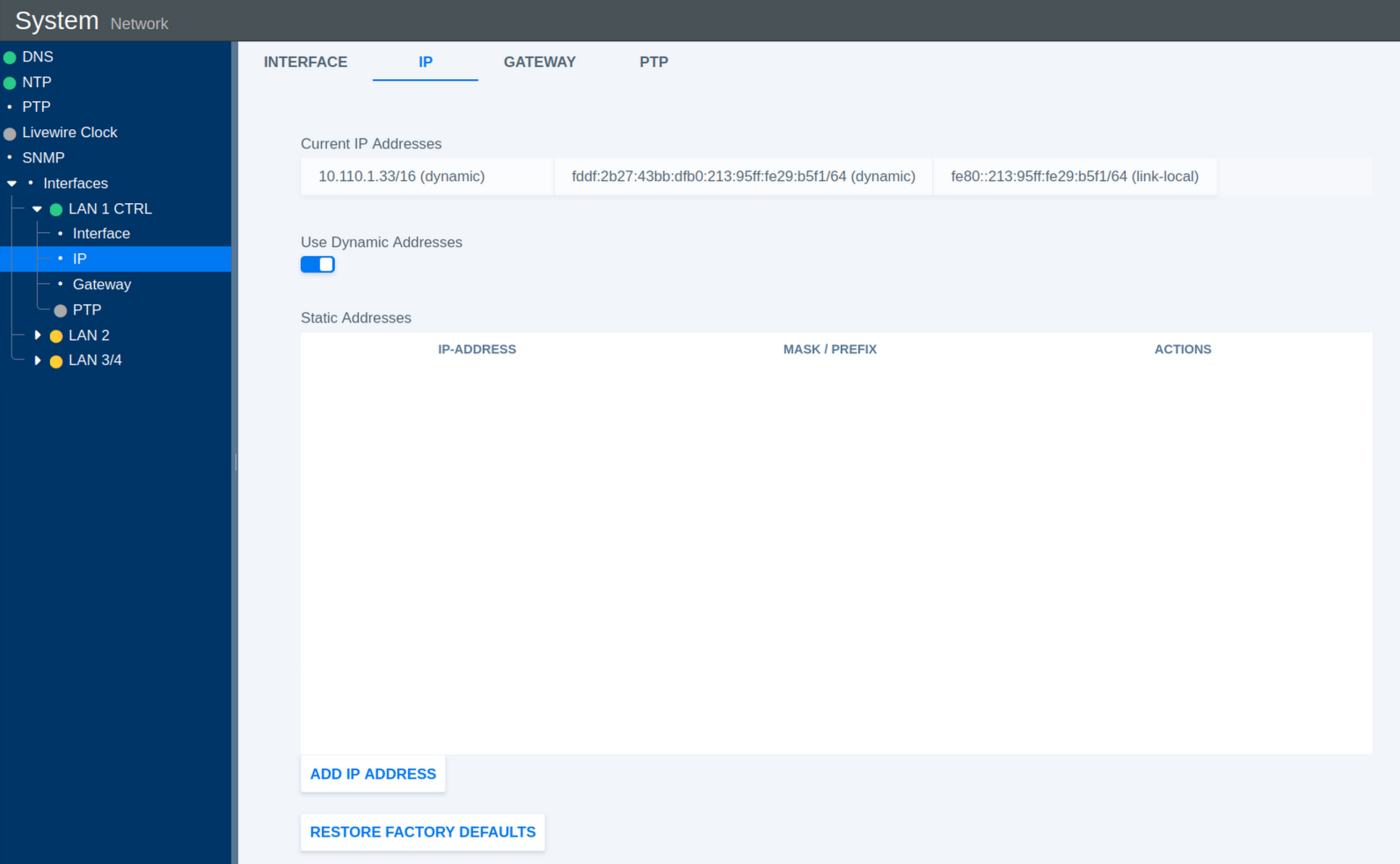
This section configures the IP addresses assigned to the selected network interface.
| Parameter | Values | Default | Description |
|---|---|---|---|
| Current IP Addresses | Status | - | Shows all IP addresses currently assigned to the interface. |
| Use Dynamic Addresses | On / Off | On | Enables or disables automatic IP address assignment using DHCP. |
| Static Addresses | Status | - | Shows the manually configured static IP addresses. |
| Add IP Address | Action | - | Opens a dialog for adding a static IP address and subnet mask or prefix. |
| Restore Factory Defaults | Toggle | Off | Restores the IP configuration of the interface to its factory defaults. |
Add Static IP Address
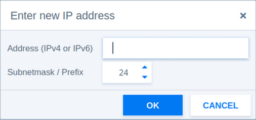
The following parameters are available when adding a static IP address manually.
| Parameter | Values | Default | Description |
|---|---|---|---|
| Address | IPv4 or IPv6 | - | Defines the static IP address. |
| Subnetmask / Prefix | 3-127 | 24 | Defines the network prefix length or subnet mask. |
| Prefix Example 1 | 24 | - | Corresponds to the IPv4 subnet mask 255.255.255.0. |
| Prefix Example 2 | 16 | - | Corresponds to the IPv4 subnet mask 255.255.0.0. |
Interfaces: Gateway
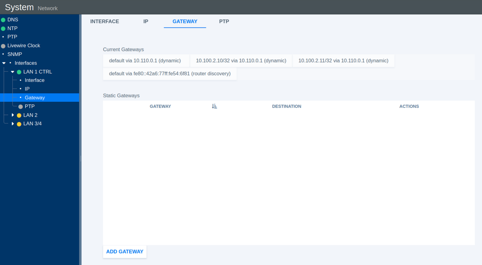
This section configures network gateways for the selected interface.
| Parameter | Values | Default | Description |
|---|---|---|---|
| Current Gateways | Status | - | Shows all currently active gateway addresses. |
| Static Gateways | Status | - | Shows manually configured static gateway addresses. |
| Add Gateway | Action | - | Opens a dialog for adding a static gateway. |
Add Static Gateway
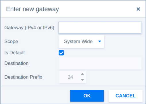
The following parameters are available when adding a static gateway manually.
| Parameter | Values | Default | Description |
|---|---|---|---|
| Gateway | IPv4 or IPv6 | - | Defines the gateway IP address. |
| Scope | System Wide / Link Specific | System Wide | System Wide makes the gateway available system-wide. Link Specific associates the gateway with the selected network interface only. |
| Is Default | Checkbox | - | Sets this gateway as the default route for traffic that does not match a more specific route. |
| Destination Prefix | 3-127 | 24 | Defines the network prefix length of the destination route. |
Interfaces: PTP
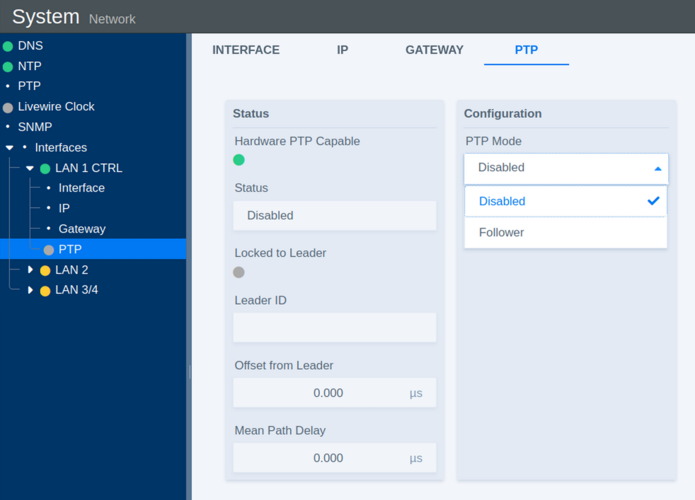
The PTP section configures Precision Time Protocol synchronization for the selected network interface.
| Parameter | Values | Default | Description |
|---|---|---|---|
| Status | Error / Enabled / Disabled | Disabled | Shows the current operational state of PTP synchronization. |
| Locked to Leader | Indicator | - | Indicates whether the system is successfully synchronized to a PTP Leader Clock. |
| Leader ID | Status | - | Shows the identifier of the current PTP Leader Clock. |
| Offset from Leader | Status | - | Shows the time deviation from the Leader Clock in nanoseconds. |
| Mean Path Delay | Status | - | Shows the measured mean network path delay for PTP communication. |
| PTP Mode | Disabled / Follower | Follower | Disabled turns off PTP synchronization on this interface. Follower synchronizes the system to an external PTP Leader Clock. |
PTP Clock Settings
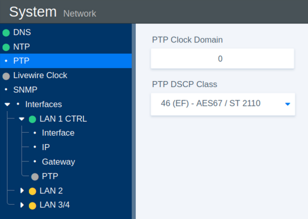
These parameters define the general PTP clock settings.
| Parameter | Values | Default | Description |
|---|---|---|---|
| PTP Clock Domain | 0-127 | 0 | Defines the PTP domain number. Only PTP devices operating in the same domain participate in the same synchronization instance. |
| PTP DSCP Class | 0-63 | 46 | Defines the Differentiated Services Code Point (DSCP) used to prioritize PTP network traffic. |
Certificates
If your flexAI system is connected to an open or untrusted network, we recommend using encrypted communication.
Starting with flexAI version 2023-12r1, secure client-server communication via HTTPS is supported. HTTPS uses TLS to encrypt the communication between the flexAI system and a client, such as a web browser or other software.
For HTTPS connections, the flexAI system provides a server certificate that allows the client to verify the server's identity and establish an encrypted connection.
Open the Certificates page to view and manage the certificates installed on the system.
By default, flexAI uses a self-signed certificate. Since this certificate is not issued by a trusted certificate authority (CA), web browsers may display a security warning when connecting to the system.
If your network uses a Certificate Authority (CA), you can generate a CSR (Certificate Signing Request) and have it signed by your CA.
Alternatively, you can import a certificate that includes the flexAI system's IP address and/or DNS name in its Subject Alternative Name (SAN) entries. If the issuing CA is trusted by the client, browsers can establish the HTTPS connection without displaying certificate warnings.
You can also download the currently installed certificate or display its details directly on the Certificates page.
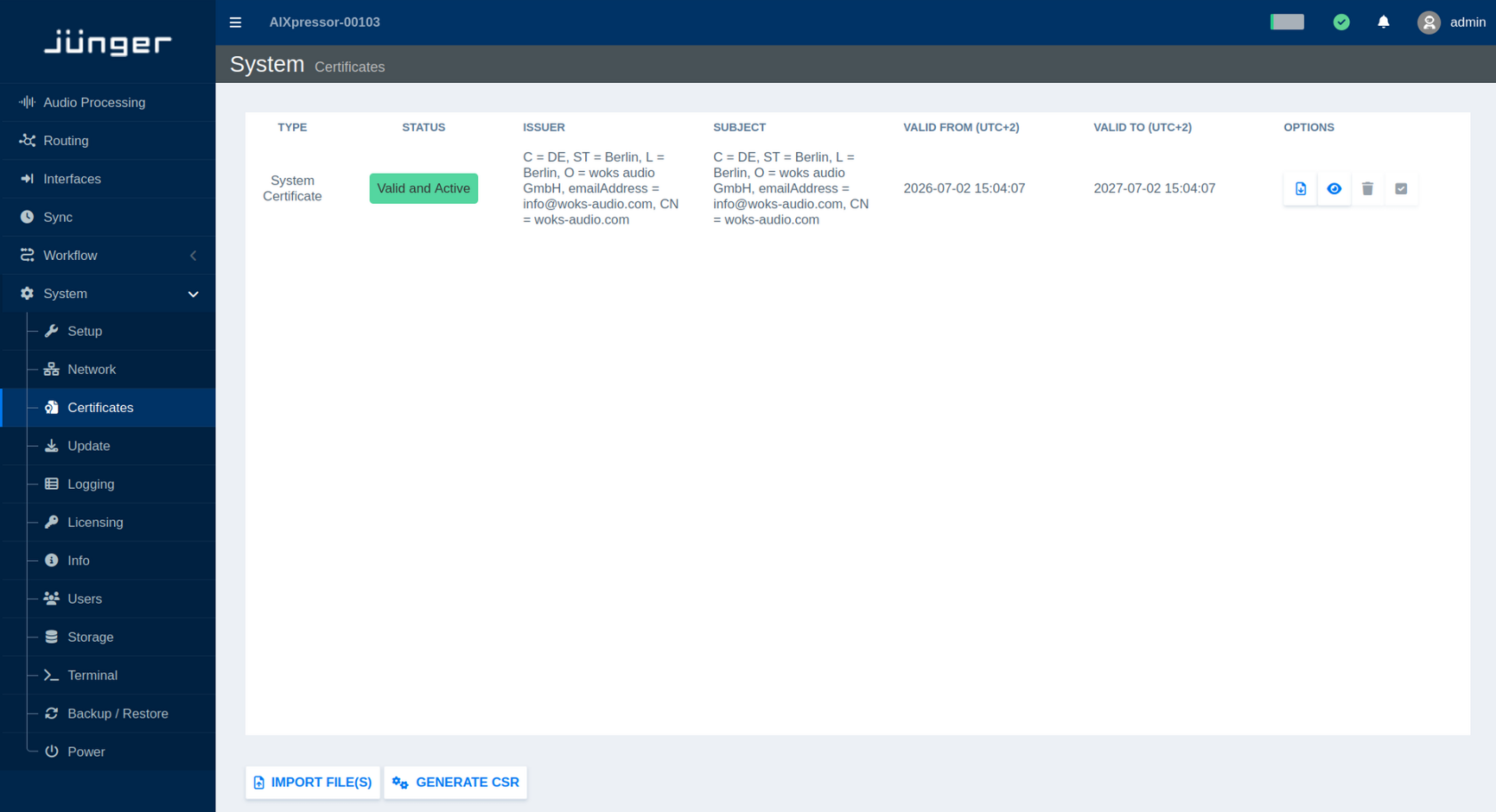
Update
Select Update from the System menu to manage software updates and installed applications.
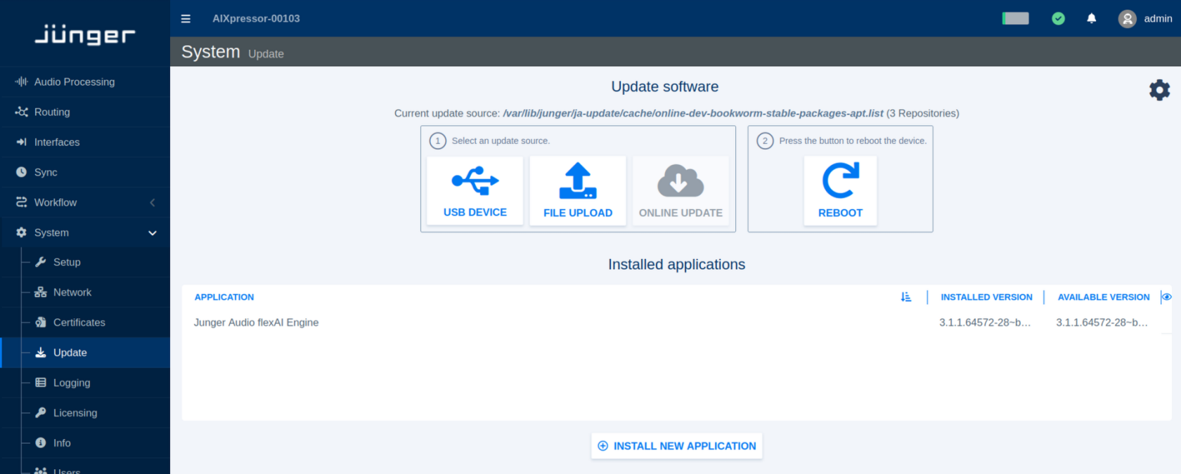
By default, the Update page provides a simplified workflow for updating the flexAI system. For installations that require more detailed package management, an Advanced View is also available.
Updating the System
In the standard view, first select the source from which the software update should be loaded:
-
USB Device – use an update available on a connected USB storage device.
-
File Upload – upload an update file from the computer running the web browser.
-
Online Update – retrieve an update from the configured online update source, if available.
After selecting the appropriate update source, follow the instructions shown on the page. The system can then be rebooted using Reboot as part of the update procedure.
The Installed applications section lists the applications currently installed on the flexAI system together with their installed and, where available, newer software versions.
Use Install New Application to add an application that is not currently installed.
Update Settings
Click the settings icon in the upper-right corner of the Update page to open the update settings.
The following options are available:
-
Automatically update packages when a new release is installed – updates installed packages automatically when installing a new software release.
-
Automatically fix broken packages when a new release is installed – attempts to repair package inconsistencies as part of a release installation.
-
Show advanced package management – enables the Advanced View described below.
-
Only show Jünger packages – limits the displayed package list to Jünger Audio packages.
For normal operation, the simplified update view is generally sufficient. Enable advanced package management when individual packages need to be inspected or managed separately.
Advanced View
When Show advanced package management is enabled, the Update page provides direct access to the individual software packages available from the configured update source.
Use the category list, package search field, and package filter to locate specific packages. The package table shows information such as the Package name, Description, Installed Version, and Available Version.
The toolbar provides the following package management functions:
-
Change Update Source – selects or changes the source from which package information and updates are obtained.
-
Mark Available Updates – marks packages for which newer versions are available.
-
Apply Changes – applies the currently selected package changes.
-
Revert Changes – clears changes that have been selected but not yet applied.
-
Reboot Device – restarts the flexAI system when required after an update or package change.
Selecting a package provides additional information and available actions in the lower part of the page.
The Advanced View is intended for installations where individual package management is required. For regular flexAI software updates, use the standard update workflow whenever possible.
Logging
flexAI provides a comprehensive logging system based on information available from the underlying Linux operating system. Log data may include messages from the Linux kernel, system services, I/O operations, and user applications. This information is stored locally on the system and can be used for later analysis.
Select Logging from the System menu to view the available log files.
The log files can be viewed directly in flexAI. Their contents are primarily intended for diagnostics and troubleshooting, for example when working with customer support. The list can be filtered for the severity of a message or to a specific app in the system.
For further troubleshooting, a Diagnostics File containing additional system information can be downloaded from System > Info
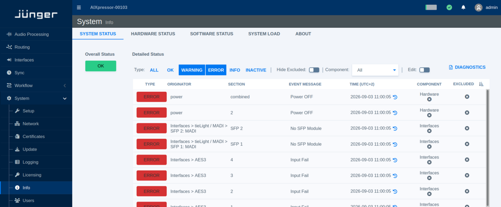
Licensing
flexAI systems use licenses to enable the flexAI engine as well as additional audio processing components, interfaces, and other optional features. Depending on the installation, licenses may be provided locally via a USB license dongle or centrally through a Wibu license server.
Select Licensing from the System menu to view the currently installed licenses.
The Product Name and Product Code identify each licensed product or feature. Quantity shows the total number of licenses available for that product, while Available shows how many of these licenses are currently not in use.
Some licenses, such as licenses provided for demonstrations or evaluations, are valid for a limited period. For these licenses, an Expiration Time is shown on the Licensing page. After this date, the corresponding licensed feature is no longer available unless the license is renewed or replaced.
When purchasing or activating additional licenses, you may be asked to provide a License Request. To create it, use Download License Context File in the lower-left corner of the Licensing page. The downloaded file contains the license context information required to generate the corresponding license update.
Once you receive the License Update File, use Upload License Update File in the lower-right corner of the page to install or update the licenses on the flexAI system.
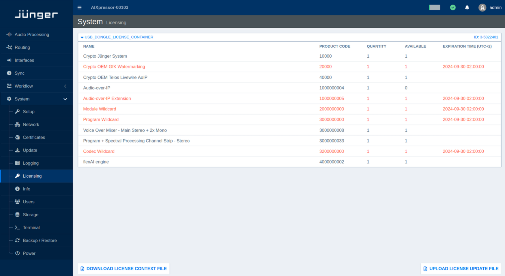
Info
The Info page provides an overview of the current status, system load, installed components, and software versions of the flexAI system.
The page is organized into five sections:
-
System Status
-
Hardware Status
-
Software Status
-
System Load
-
About
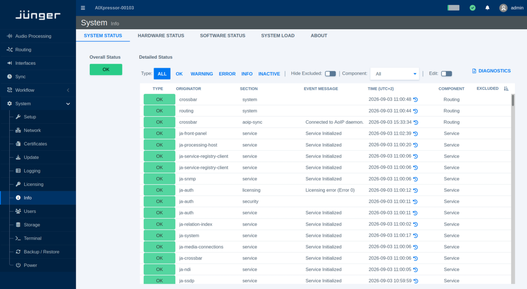
System Status
Select Info from the System menu to open the Info page. The System Status section is displayed by default.
The Overall Status indicator shows the general operational state of the flexAI system. A green OK status indicates that the system is operating normally overall. Individual components may still report informational messages, inactive states, or non-critical warnings.
The Component drop-down menu allows you to filter the status information by component group. Available groups include All, Service, System, Hardware, Audio Processing, Routing, Sync, Network, and Interfaces.
Use Edit to customize how individual status entries are handled. A status can be excluded from the calculation of the Overall Status, so that changes to this status no longer affect the general system status indication. Status entries that are not relevant for a particular installation can also be hidden completely from the System Status view (Hide Excluded).
These settings allow the status overview to be adapted to the requirements of a specific system without disabling the underlying status monitoring.
Each individual status entry provides access to its history. Click the history icon next to a status to open the Status History dialog. The dialog lists previous state changes together with their timestamp, status type, event message, and any available details. It also identifies the corresponding originator, section, and component.
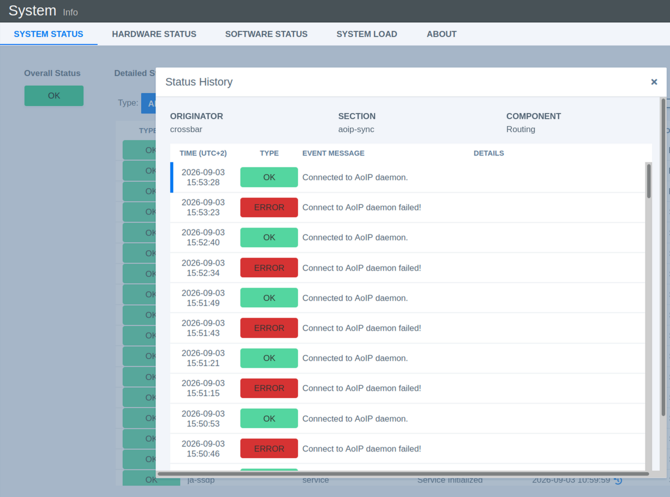
This history can be useful when investigating intermittent issues, as it allows you to see when a status changed and whether it subsequently returned to its normal state.
Diagnostics File
Click Diagnostics on the Info page to open the Download Diagnostics File dialog.
Select the desired level of detail:
- Short creates a smaller diagnostics file containing the information typically required for troubleshooting.
- Complete collects more extensive diagnostic information and may take considerably longer to create.
Click Create and Download File to generate and download the Diagnostics File. When creating a Complete file, keep the page open until the process has finished.
If a Diagnostics File has already been created, information about the most recently created file is also available in the dialog.
Hardware Status
The Hardware Status section provides detailed information about the hardware components of the flexAI system. It is primarily intended for diagnostics and service purposes.
Depending on the system, the displayed information may include firmware versions, temperatures, fan status, and power supply status.
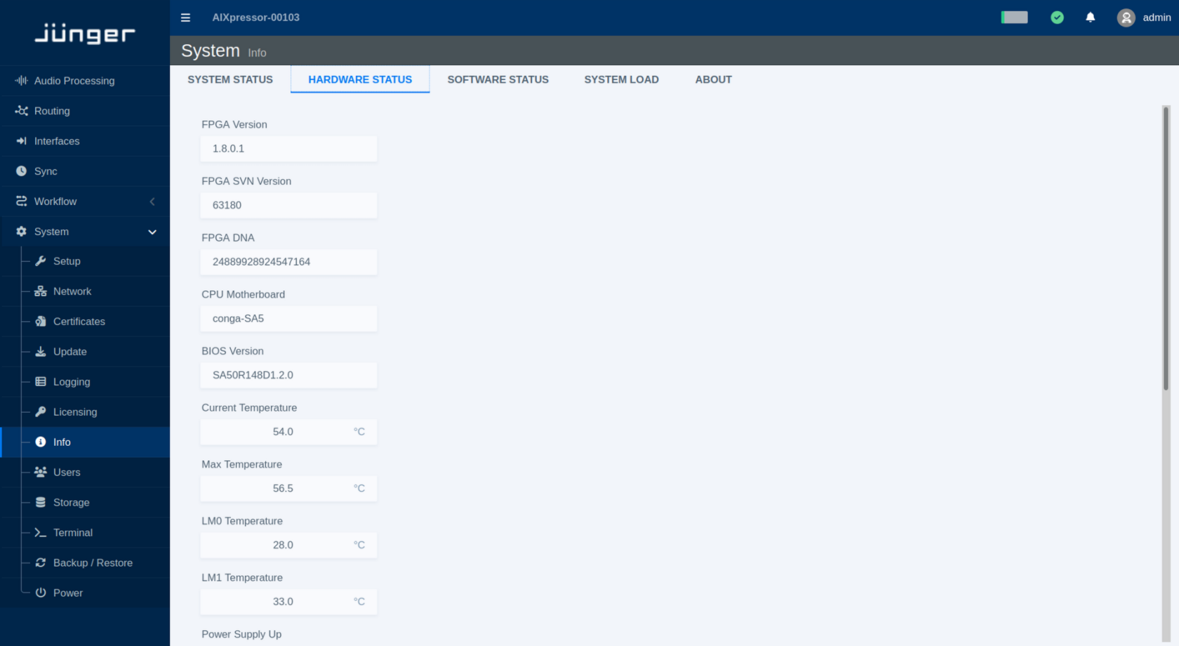
Software Status
The Software Status section lists information about the software components and versions currently installed on the flexAI system.
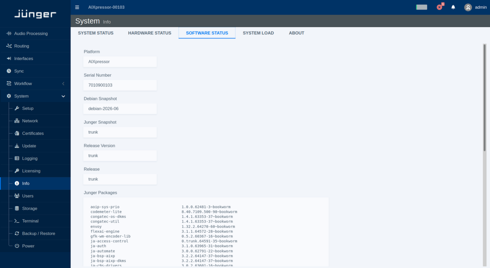
System Load
The System Load section provides an overview of the current processing load of the flexAI system.
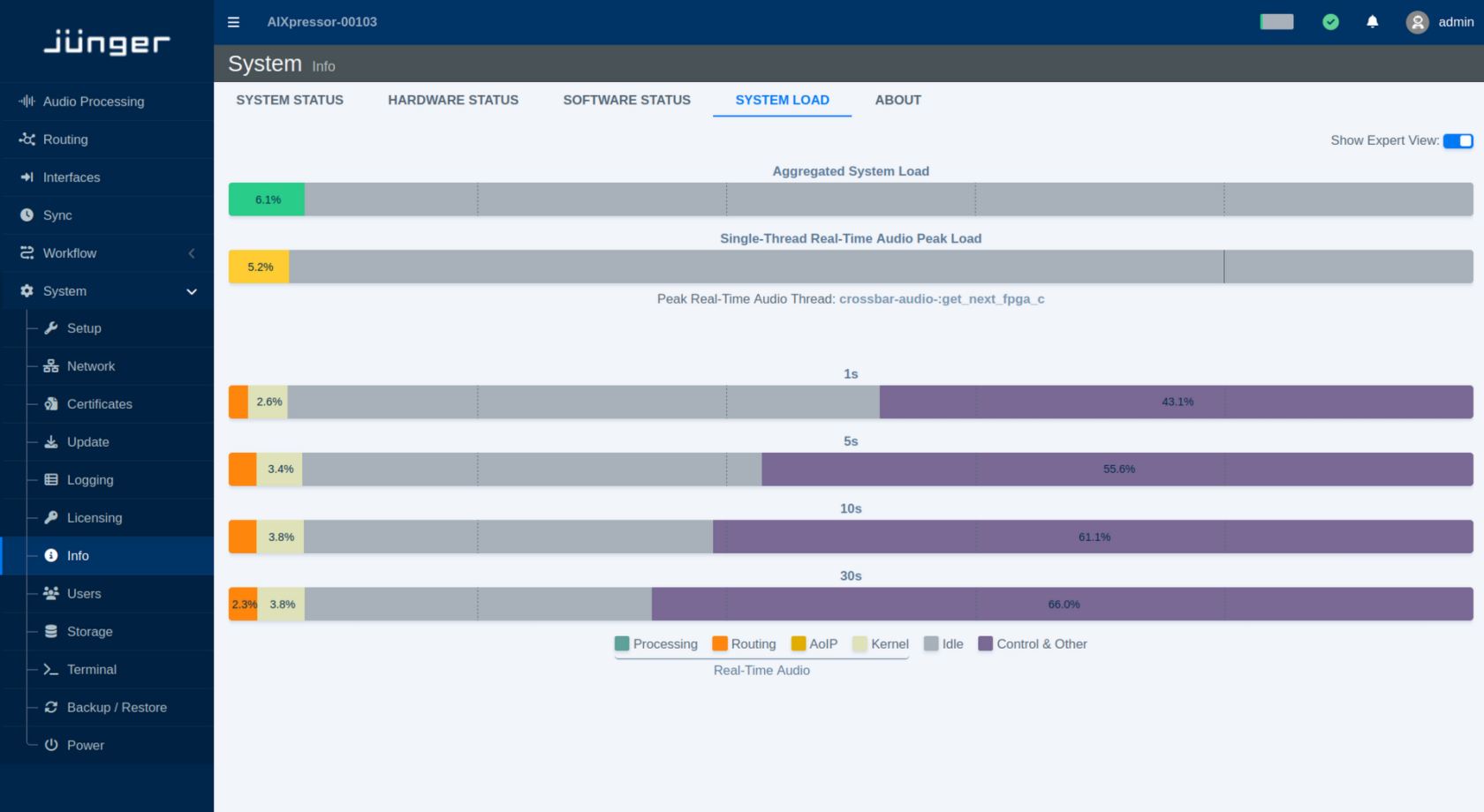
Aggregated System Load shows the overall system load and provides a quick indication of the available processing capacity.
Enable Show Expert View to display more detailed load information. The Single-Thread Real-Time Audio Peak Load shows the peak load of an individual real-time audio processing thread.
The Expert view also provides four system load bars with integration times of 1 s, 5 s, 10 s, and 30 s. Each bar is divided into color-coded sections showing how the system load is distributed across the following functions:
-
Processing
-
Routing
-
AoIP
-
Kernel
-
Real-Time Audio
-
Idle
-
Control & Other
The different integration times provide views of the system load over different time periods. Shorter integration times make brief changes in load more visible, while longer integration times provide a more stable view of the overall load distribution.
Users
Current Scope
The current flexAI version provides only a limited set of user management functions. At this stage, user administration is mainly intended for basic account access and password handling.
This article covers the available functions in the current version and will be updated as user management is extended in future releases.
Changing Passwords
To change the admin password:
Note - Password must contain at least 10 characters, including at least: - one upper case letter - one lower case letter - one number - one special character
Storage
The Storage page is currently provided for informational purposes only.
It displays an overview of the system's storage devices, partitions, and their current usage. No storage configuration or management is currently performed from this page.
Terminal
The Terminal page provides access to a web-based Linux terminal on the flexAI system.
Log in using the same credentials as for the regular flexAI user login.
The terminal can be used for standard Linux commands that do not require elevated privileges, for example htop for monitoring system processes and resource usage.
Commands that require sudo or other administrative privileges are not available through the standard user account.
If you are not familiar with the Linux command line, it is best to use the Terminal only when instructed by customer support or another experienced user. Even without administrative privileges, some commands can affect running processes, files, or system behavior.
Backup / Restore
The Backup / Restore page allows you to save the current flexAI configuration to a backup file and restore a previously saved configuration.
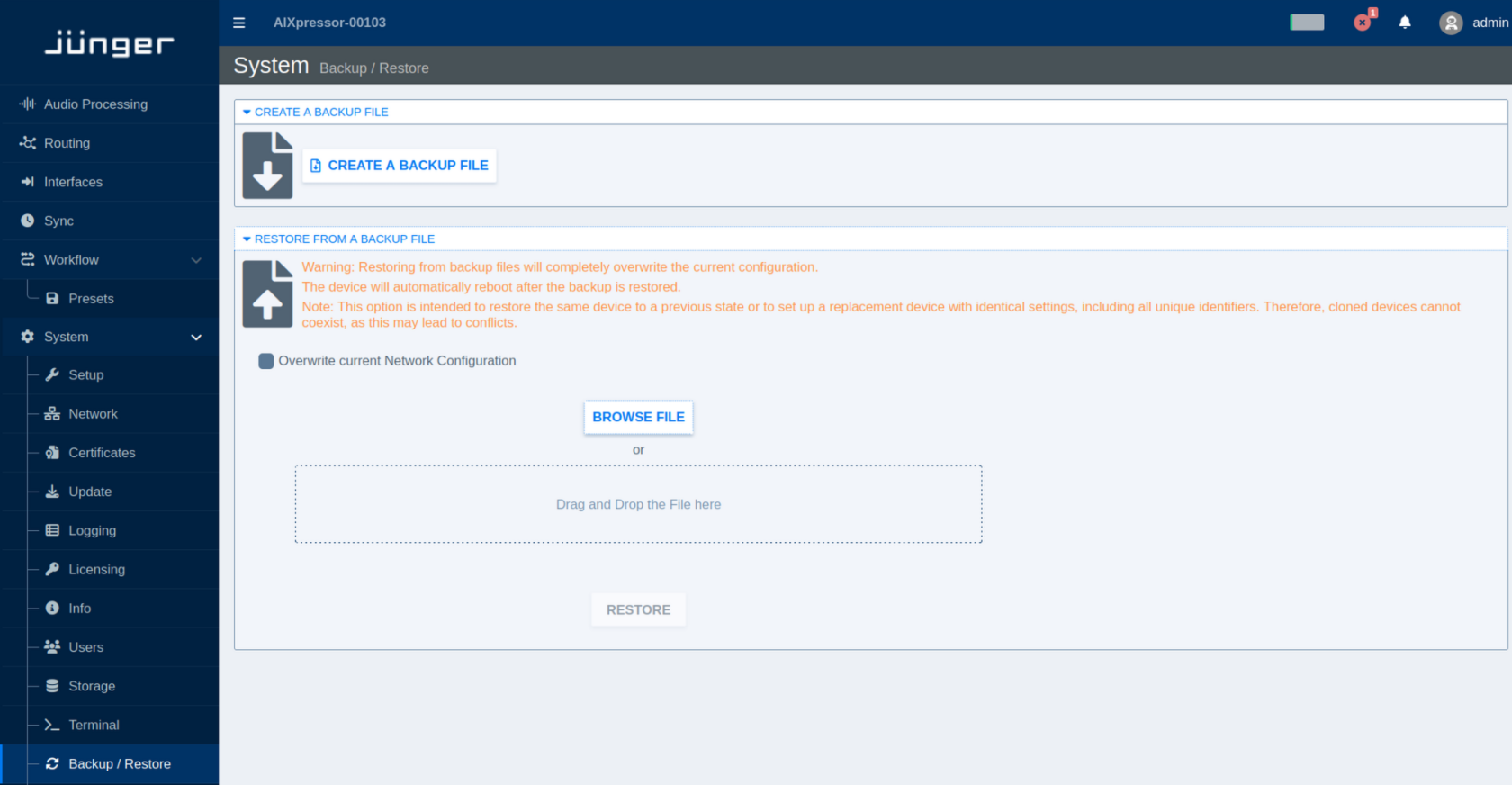
Create a Backup
Select Backup / Restore from the System menu.
Click Create a Backup File to generate and download a backup of the current system configuration. Keep backup files in a safe location so that a known configuration can be restored when required.
Restore from a Backup
A backup can be used to restore a flexAI system to a previous configuration or to configure a replacement system with the same settings.
To select a backup file, click Browse File or drag and drop the file into the designated area. Once a valid backup file has been selected, click Restore to start the restore process.
Restoring a backup replaces the current configuration with the configuration stored in the backup file. The flexAI system automatically reboots after the restore process has completed.
By default, the current network configuration is retained. Enable Overwrite current Network Configuration if the network settings stored in the backup should also be restored.
A backup may contain system-specific settings and unique identifiers. Restoring the same backup to multiple systems can therefore result in duplicate identifiers and network or service conflicts. Backup files intended to reproduce a complete system configuration should be used for restoring the original system or for setting up its replacement, rather than for creating multiple simultaneously operated copies.
Power
Select Power from the System menu to access the power controls.
Click Reboot to restart the flexAI system without removing power.
Click Shutdown to shut down the system in a controlled manner. Once the shutdown process has completed, the system can be disconnected from its power source if required.
Use Shutdown before switching off external power supplies or unplugging the system. This allows running services and the operating system to terminate properly and helps avoid incomplete writes or configuration data corruption.