
FM Conditioner
Applicability
This description applies to the Stereo version of the FM Conditioner module.
Overview
FM Conditioner is a module for preparing a stereo program signal for FM transmission-related workflows. It includes operating level, pre-emphasis, low-pass filtering, true peak limiting, and MPX-related controls.
Processing Principle
The module conditions the stereo signal according to FM-related level and deviation targets. It can apply pre-emphasis limiting, true-peak limiting, and control the MPX output.
"A Cool Setup Guide To Optimized Deviation"
FM radio broadcast is not only about audio. Instead the signal consists of different services that share the ‘space’ available on the FM carrier. A typical stereo radio signal spectrum may look like this
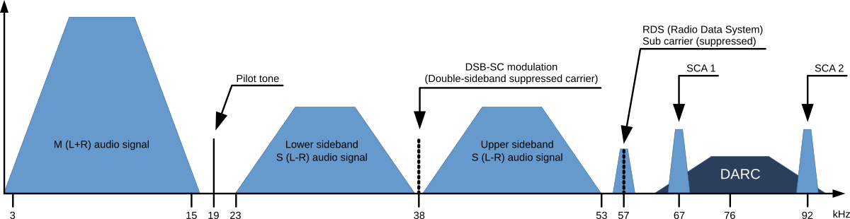

Typical FM modulation spectrum
-
Mono audio signal (M=L+R) - 30 Hz to 15 kHz base band
-
Stereo pilot tone at 19 kHz - approximately 9 % of 75 kHz deviation
-
Stereo audio signal (S=L-R) - 30 Hz to 15 kHz base band
-
DSB-SC carrier - Double-sideband suppressed carrier
-
RDS signal - Radio Data Signal at 1 187,5 Bit/s
-
DARC signal - Data Radio Channel at about 16 000 Bit/s
-
SCA signal - 14 kHz (narrow) or 26 kHz (wide) bandwidth for auxiliary audio services
To calculate the overall MPX Power the power spectrum of all consisting signals needs to be considered.
Please note that within the FM Conditioner Web UI, only RDS and SCA Deviation can be set as additional services. As SCA and DARC normally cannot be used simultaneously due to their overlapping frequency bands, the SCA Deviation parameter can also be used for DARC. To calculate the overall deviation, all of the services in use must be taken into account to ensure that they do not exceed the modulation limits defined by the ITU (as shown below). After setup, this process happens internally and is not a concern for the FM Conditioner user.
When dealing with processing for FM broadcast, four main parameters come into focus:
-
Deviation Δf of the transmission frequency (carrier) fc
-
MPX Power of the modulating signal (modulator)
-
Pre-Emphasis to enhance the signal-to-noise ratio of FM transmission
-
Baseband bandwidth of all involved services (audio signals and auxiliary data)
ITU-R BS.412
ITU-R BS.412 has standardized the maximum values for these parameters. Broadcasters must comply with these limits to not exceed the planned coverage or interfere with adjacent programs. They are:
-
Maximum peak deviation of +75 kHz
-
Maximum MPX Power of 0 dBr
-
A typical audio baseband cutoff at 15 kHz to ensure undisturbed transmission of the 19 kHz stereo pilot tone
-
For mono operation a typical audio baseband bandwidth of 17.5 kHz is utilized (no pilot tone is necessary)
Calibration
MPX Power is measured at random intervals of 60 seconds. An MPX Power level of 0 dBr should be equivalent to the modulation power of a stationary sine signal that induces a deviation of +19 kHz. A stimulus frequency of 500 Hz is recommended.
The tasks required to comply with this rule may sound 'simple' on the surface: take your pocket power measurement instrument, connect it to your readily accessible reference antenna, tune it to your transmitter, and take measurements. Then, adjust the relevant audio parameters if necessary. However, as this approach is not applicable for studio equipment, we must calculate MPX Power before modulation and then translate it to the studio output. To ensure precise calculations, all technical equipment must be gain-matched and calibrated.

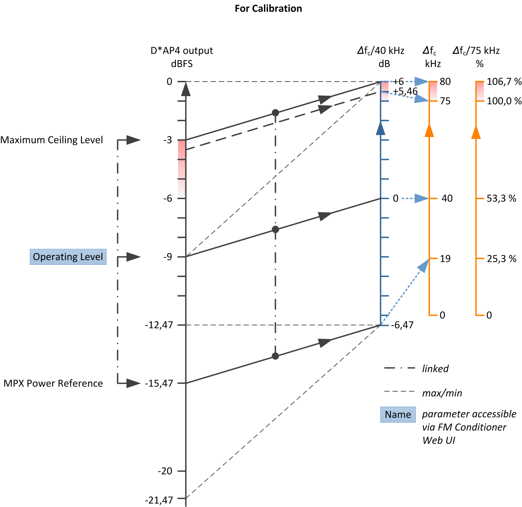
Relation of audio levels and modulation deviation during calibration
The crucial step in calibration is setting the Operating Level. A stationary sine signal at this level should induce a 40 kHz deviation in the FM carrier. If the input level (at the FM HPA or uplink line) for this reference modulation is known, simply configure the Operating Level in the FM Conditioner accordingly. This is applicable in most installations.
In many stations, the reference level for a 500 Hz tone is +6 dBu (analog) or -9 dBFS (digital). It may be designated as the operating level and defined at 0 dB relative (as displayed on a peak level meter). However, please exercise caution with this type of reference level scale, as this analog operating level of 0 dBr is not the same as 0 dBr MPX Power.
If the reference modulation is unknown, you need to apply a sine test tone and measure the frequency deviation of the FM carrier over the air. Start with a generator level of -9 dBFS and adjust this value until you achieve a 40 kHz deviation. It's important to note that any processing in the signal chain between the generator and FM HPA must be bypassed during calibration. The calibration process should be carried out without considering any processing, additional services, or pilot signals.
If the Reference Level of your setup differs from -9 dBFS, you can use the Setup Gain of the FM Conditioner for level matching.
The second step of calibration involves configuring the values for the Pilot Tone, RDS, and SCA (DARC) Deviation. The required values depend on the settings of the respective encoders. Please refer to their manuals.
After completing the calibration process, the FM Conditioner will display the available audio headroom.
Here is an example with an assumed deviation of ~ 12 % of 75 kHz for the extra services:
20*log (75 kHz – 8.8 kHz) / 40 kHz = 4,4 dB
Or -4.6 dBFS
Operation
All calculation is performed internally and updates automatically whenever any of the involved parameters change. The resulting value is referred to as the 'Ceiling.' It's essential to understand that the Ceiling is calculated with the Pre-Emphasis filtering of the FM transmitter included. Therefore, the wideband true peak level of the audio signal before Pre-Emphasis must be lower. To better grasp this concept, you can refer to the level relation diagram:
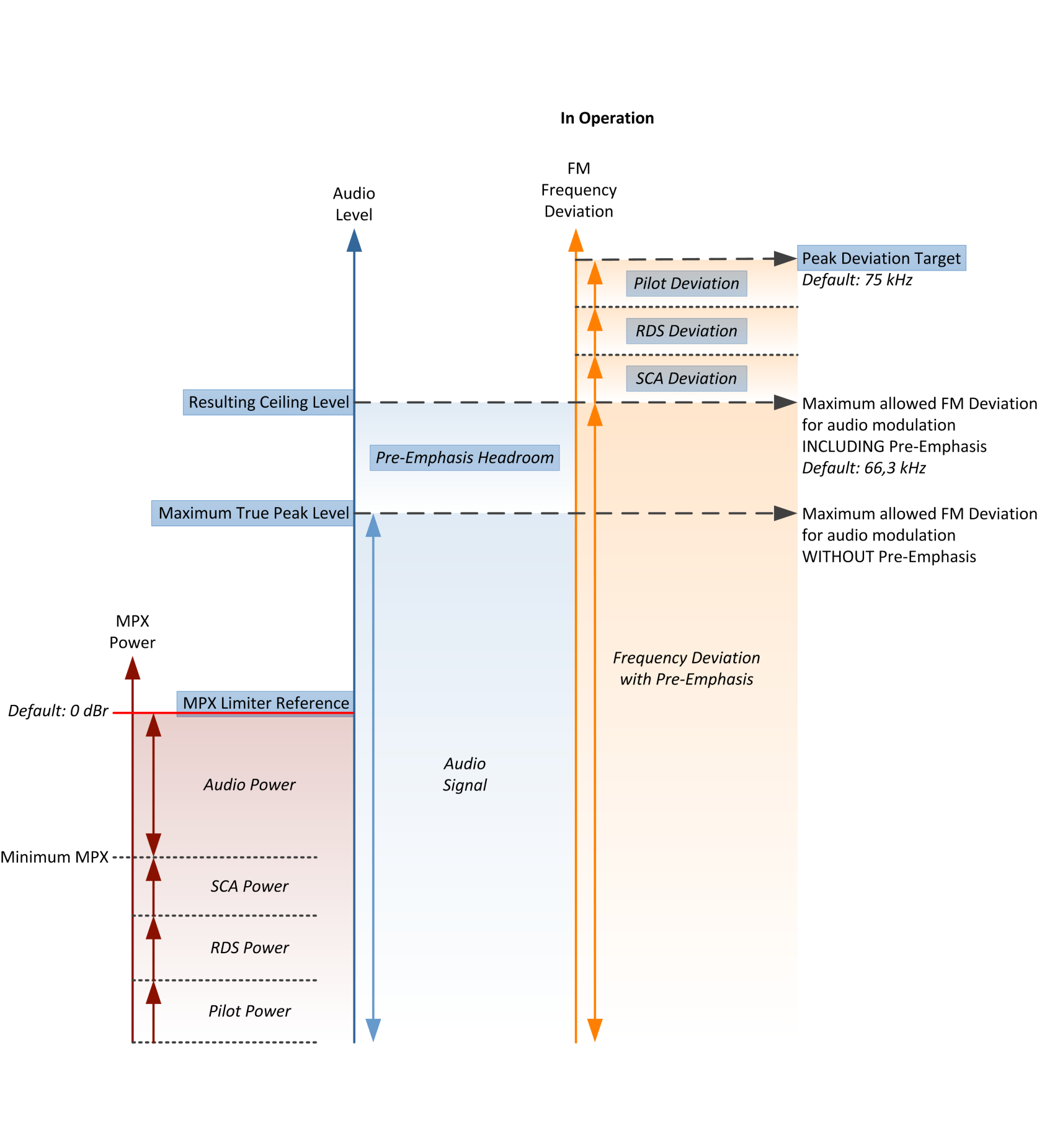

Relation of audio levels and modulation deviation in operation
Pre-Emphasis
Pre-Emphasis is a filtering system in which higher frequencies are boosted by a shelving filter at the transmission stage and conversely reduced at the receiver end. The Pre-Emphasis filter employs a time constant of 50 µs (or 75 µs in the USA), resulting in a 10 dB gain at 10 kHz. This process significantly improves the signal-to-noise ratio. However, as the increased high-frequency energy contributes to the MPX Power, it must be taken into account within the FM Conditioner.
There are two mechanisms to manage Pre-Emphasis. First, a Pre-Emphasis Headroom parameter reduces the maximum wideband level by lowering the true peak limiter threshold. This results in lower overall audio levels but enhanced high-frequency transparency. Second, a process called Pre-Emphasis Limiter dynamically reduces the high-frequency component of the audio signal, creating 'space' for the additional Pre-Emphasis shelving. The Pre-Emphasis Limiter is always active and prevents high-frequency overmodulation. To lessen its impact, the Pre-Emphasis Headroom should be increased. The Pre-Emphasis Limiter is based on sophisticated dynamic filter algorithms, well-known from the state-of-the-art Jünger Audio De-Esser.
It's important to note that very short transients may not be fully mitigated by the Pre-Emphasis Limiter. Nevertheless, this is a fundamental aspect and has no practical significance for FM transmission.
True Peak Limiter
The Maximum True Peak value cannot be manually set by the user since it is automatically calculated and set to the Ceiling Level minus the Pre-Emphasis Headroom. When there's no Pre-Emphasis Headroom, the Maximum True Peak equals the Ceiling.
The MPX Limiter algorithm
The most crucial component of the FM Conditioner processor is undoubtedly the MPX Limiter. Since MPX Power is a value calculated over one minute of integration time, limiting can be a highly intricate task. In theory, a 60-second look-ahead time may seem appropriate, but it's not practically feasible for a real-time processor. Therefore, the Jünger Audio MPX Limiter employs a complex prediction algorithm that adapts to the incoming signal structure. Nevertheless, the limiter reference level remains an absolute brickwall threshold and is considered inviolable. In the event of an 'emergency,' the MPX Limiter will drastically reduce the signal level to prevent any threshold violation. The MPX Limiter in the FM Conditioner can be considered the most effective MPX brickwall limiter available today.
Please be aware that the MPX Limiter Reference can, of course, be exceeded when incoming levels are high and the MPX Limiter has just been activated. According to the measurement principle, it may take up to one minute for the MPX Limiter to stabilize
The MPX Limiter Profile impacts the speed and extent of the process and, consequently, its neutrality toward incoming sound quality. When using softer settings, the system requires a buffer zone between the MPX Limiter reference and the measured MPX of the audio signal. Although this buffer zone is always very small, with harder settings, it becomes even smaller, allowing for higher MPX Power transmission. The optimal setting depends on the type and style of the program being broadcast.
Parameters
General and Filtering
|
Parameter - General and Filtering |
Description |
|
FM Conditioner Enable |
Enables or disables the FM Conditioner stage. |
|
Operating Level |
Sets the operating level used by the FM conditioning process. |
|
Setup Gain |
Adjusts the setup gain before FM conditioning. |
|
Low-pass Filter Enable |
Enables or disables the low-pass filter the protects the pilote tone from interference with the audio signal. |
|
Pre-emphasis |
Selects or configures the pre-emphasis behavior. |
|
Pre-emphasis Headroom |
Sets the headroom used for pre-emphasis processing. |
|
True Peak Limiter Profile |
Selects the true peak limiter timing profile used by the FM conditioning path. |
MPX and Deviation
|
Parameter - MPX and Deviation |
Description |
|
MPX Enable |
Enables or disables MPX limiting. |
|
MPX Limiter Profile |
Selects the MPX limiter timing profile. |
|
MPX Reference |
Sets the MPX reference level. |
|
Peak Deviation Target |
Sets the target peak deviation. |
|
Pilot Deviation |
Sets the pilot deviation value. |
|
RDS Deviation |
Sets the RDS deviation value. |
|
SCA Deviation |
Sets the SCA deviation value. |
|
Reset Max |
Resets maximum value tracking in the meters when applied or when a preset is loaded. |
Metering
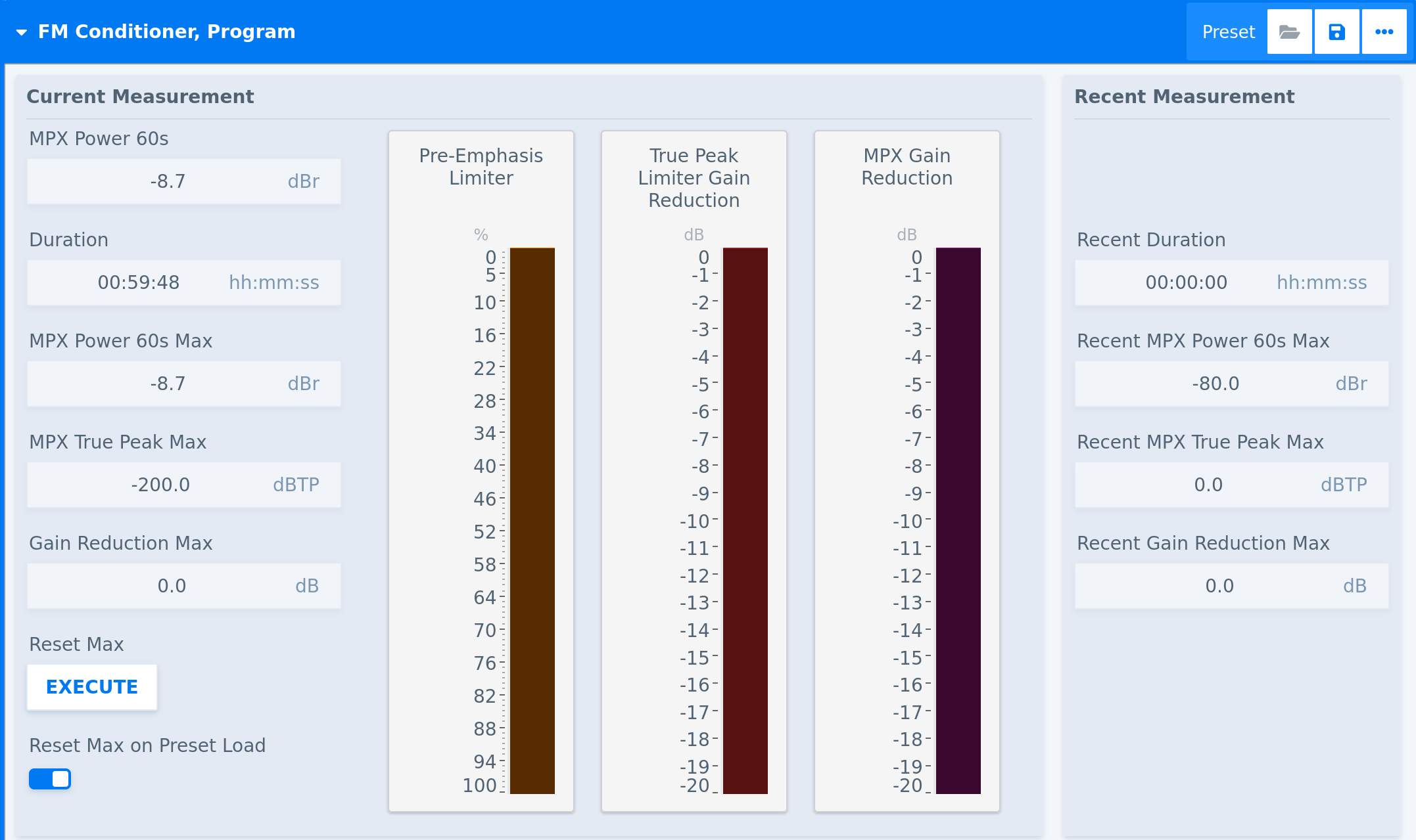
|
Parameter - Measurement |
Description |
| Reset Max |
Triggers the reset of the Current Measurement cycle and writes its values in the Recent Measurement section on the right-hand side of the meters. |
|
Reset Max on Preset Load |
Triggers the aforementioned reset when a preset is loaded. |
Related Processors
-
FM Conditioner Channel Strip - Stereo