
Audio over IP - Senders
Senders
The Senders (TX) section under AoIP contains the transmit streams configured on the flexAI system.
Use ADD to create a new sender. Existing senders are listed below Senders (TX) and can be selected individually for configuration. Use DEL to remove selected senders.
Some sender parameters are only visible when Show Expert Settings is enabled.
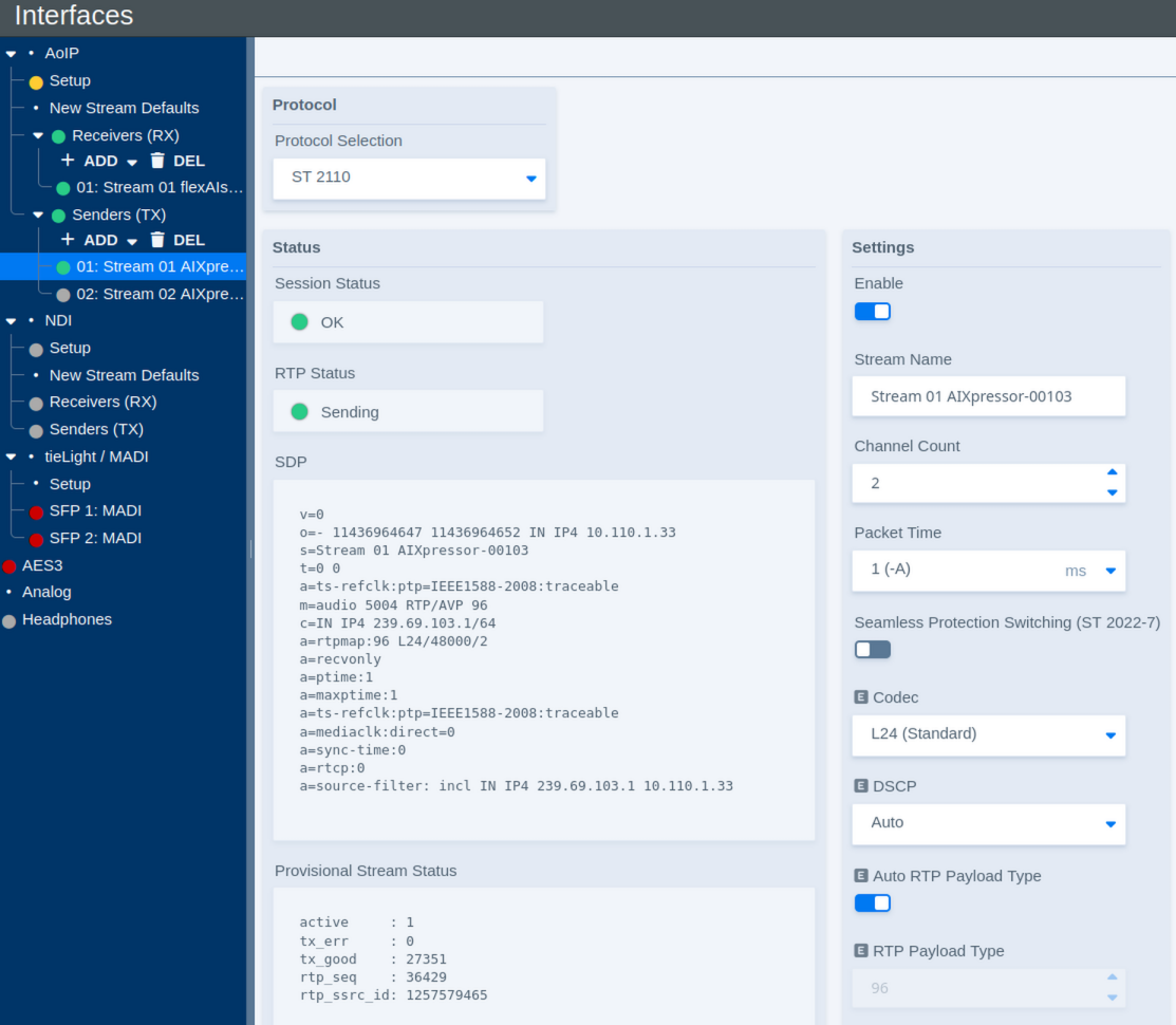
Protocol
| Parameter | Values | Default | Description |
|---|---|---|---|
| Protocol Selection | Available AoIP protocols | - | Selects the protocol used by the sender. The available settings may change depending on the selected protocol. |
Status
The Status section shows the current operating state of the sender and provides the SDP describing the transmitted stream.
| Parameter | Values | Default | Description |
|---|---|---|---|
| Session Status | Status | - | Shows the overall status of the transmit session. |
| RTP Status | Status | - | Shows whether RTP packets are currently being transmitted. |
| SDP | Status / SDP data | - | Shows the Session Description Protocol data generated for the transmitted stream. This information can be used to configure compatible receivers. |
| Provisional Stream Status | Diagnostic information | - | Provides detailed sender statistics and diagnostic information about the outgoing RTP stream. |
| Reset Sender Status | Button | - | Resets the displayed sender status and diagnostic counters. |
| RTP Status – Leg 1 | Status | - | Shows the transmit status of the first stream leg. |
| RTP Status – Leg 2 | Status | - | Shows the transmit status of the redundant second stream leg when ST 2022-7 is used. |
To copy the complete SDP, move the pointer over the displayed SDP. A copy control appears; click it to copy the SDP to the clipboard. The copied SDP can then be pasted directly into a compatible receiver or another application.
The Provisional Stream Status is primarily intended for diagnostics and troubleshooting. For normal operation, the Session and RTP status indicators provide the most relevant overview.
Settings
The Settings section defines the format and network properties of the transmitted stream.
| Parameter | Values | Default | Description |
|---|---|---|---|
| Enable | On / Off | - | Enables or disables the sender. |
| Stream Name | Text | - | Defines the name used to identify and advertise the transmitted stream. |
| Channel Count | Supported channel counts | - | Defines the number of audio channels carried by the stream. |
| Packet Time | Supported packet times | - | Defines the duration of audio carried by each RTP packet. Shorter packet times reduce transport latency but increase the packet rate and processing load. |
| Seamless Protection Switching (ST 2022-7) | On / Off | - | Enables SMPTE ST 2022-7 seamless protection switching. When enabled, two equivalent stream legs are transmitted over separate network paths. |
| Codec | Available codecs | - | Defines the audio codec or sample format used for the transmitted stream. |
| DSCP | Auto / Available DSCP values | - | Defines the Differentiated Services Code Point used to classify the outgoing RTP traffic for Quality of Service (QoS). Auto applies the DSCP value configured for the corresponding stream type and packet time on the AoIP Setup page. |
| Auto RTP Payload Type | On / Off | - | Automatically assigns the RTP payload type. Disable this option to specify the payload type manually. |
| RTP Payload Type | RTP payload type | - | Defines the RTP payload type when automatic assignment is disabled. |
| RTP Port | Port number | - | Defines the UDP destination port used for the RTP stream. |
| TTL | Number of network hops | - | Defines the IP multicast Time To Live (TTL), limiting how many routed network hops the multicast stream can traverse. |
DSCP (Differentiated Services Code Point) allows network infrastructure to classify AoIP traffic for Quality of Service. Switches and routers can use this marking to give time-critical audio traffic the required priority over less critical network traffic.
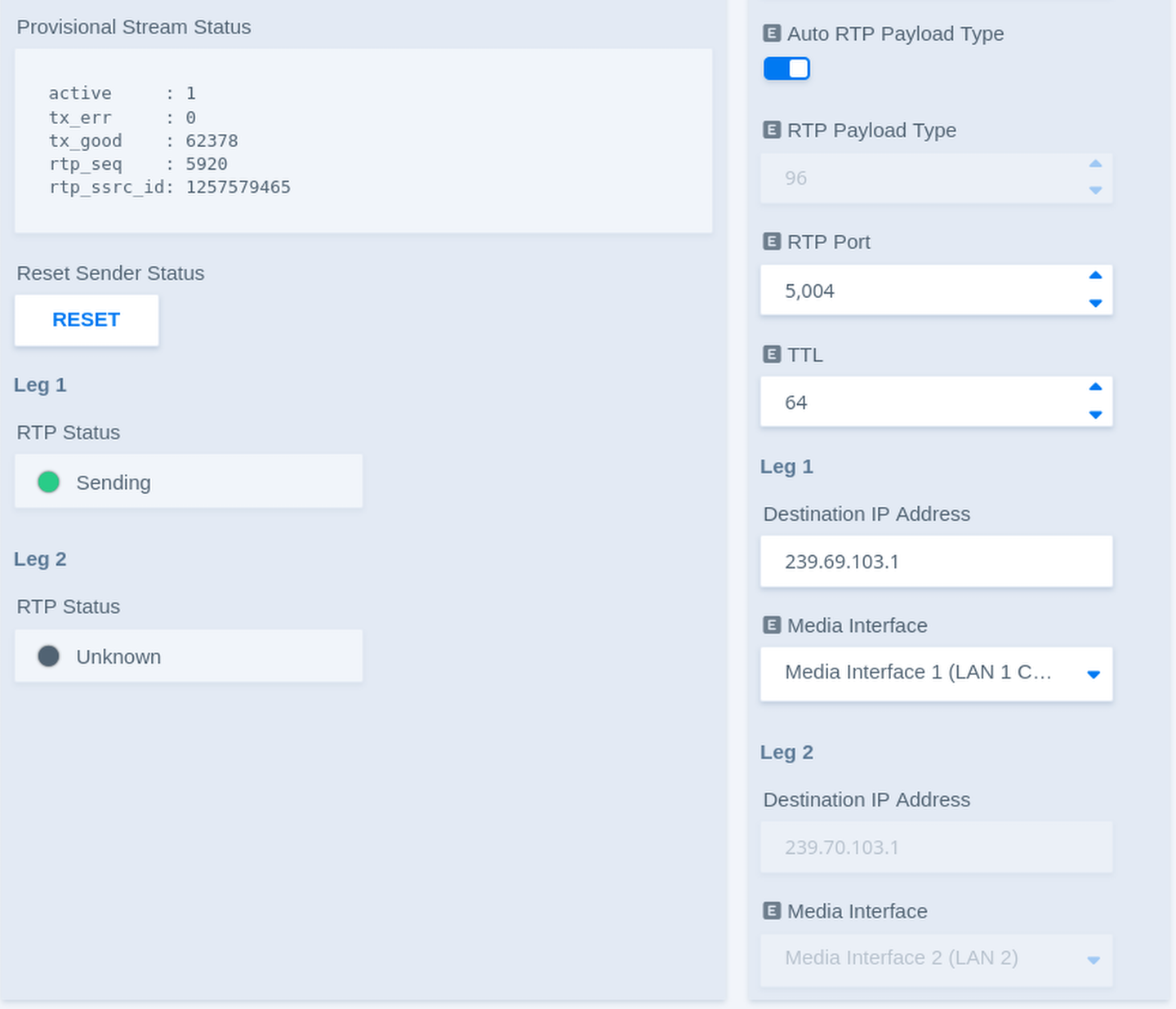
Stream Legs
Each sender can use up to two stream legs. Leg 1 carries the primary stream. Leg 2 carries an equivalent redundant stream when ST 2022-7 is enabled.
| Parameter | Values | Default | Description |
|---|---|---|---|
| Destination IP Address – Leg 1 | Multicast IP address | - | Defines the multicast destination address used to transmit the first stream leg. |
| Media Interface – Leg 1 | Available Media Interfaces | - | Selects the Media Interface used to transmit the first stream leg. |
| Destination IP Address – Leg 2 | Multicast IP address | - | Defines the multicast destination address used to transmit the redundant second stream leg. |
| Media Interface – Leg 2 | Available Media Interfaces | - | Selects the Media Interface used to transmit the redundant second stream leg when ST 2022-7 is enabled. |
Each sender can be assigned individually to one of the available Media Interfaces. This allows different senders, and, with ST 2022-7, individual stream legs, to use separate physical AoIP networks.
In combination with the internal audio routing, flexAI can also transfer audio between otherwise independent AoIP networks: audio received through one Media Interface can be routed internally and transmitted again through a sender assigned to another Media Interface. This operates at the audio level rather than as a network bridge.
With ST 2022-7 enabled, both legs carry equivalent audio data over independent network paths. A compatible receiver can use both legs for seamless protection against packet loss or a failure of one network path.
Livewire Sender Settings
When Livewire is selected under Protocol Selection, some sender parameters differ from those used for ST 2110.
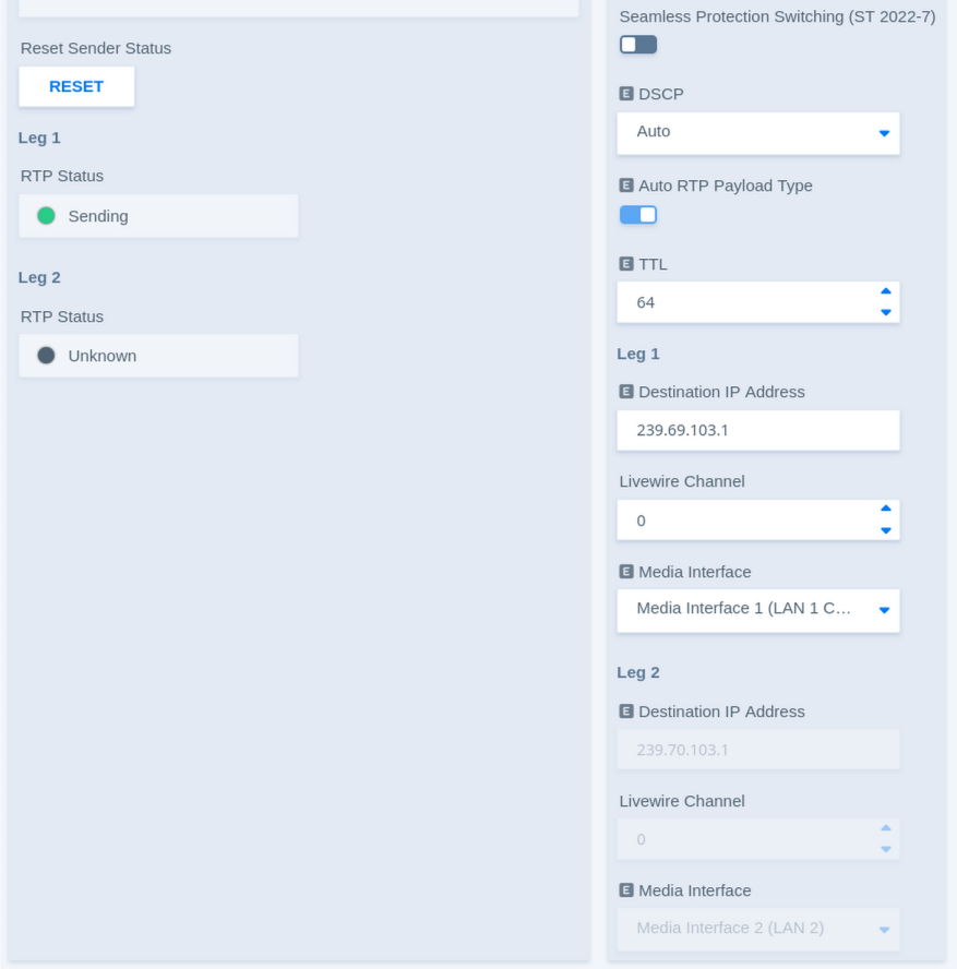
The general sender controls, status information, packet time, DSCP, and redundancy settings operate in the same way as described above. Livewire additionally uses a Livewire Channel to identify the transmitted stream.
| Parameter | Values | Default | Description |
|---|---|---|---|
| Destination IP Address – Leg 1 | Multicast IP address | - | Shows or defines the multicast destination address used for the first Livewire stream leg. |
| Livewire Channel – Leg 1 | Livewire channel number | - | Defines the Livewire Channel used for the first stream leg. The channel number identifies the stream within the Livewire network and corresponds to its multicast destination. |
| Media Interface – Leg 1 | Available Media Interfaces | - | Selects the Media Interface used to transmit the first Livewire stream leg. |
| Destination IP Address – Leg 2 | Multicast IP address | - | Shows or defines the multicast destination address used for the redundant second Livewire stream leg. |
| Livewire Channel – Leg 2 | Livewire channel number | - | Defines the Livewire Channel used for the redundant second stream leg. |
| Media Interface – Leg 2 | Available Media Interfaces | - | Selects the Media Interface used to transmit the redundant second stream leg when ST 2022-7 is enabled. |
As with other sender types, Leg 2 is used when Seamless Protection Switching (ST 2022-7) is enabled.